


®
Wireless Load Cell ±50N
PS
-
3216
10
013-15734A
Appendix B: Calibration
Calibration is not necessary, especially if you are
measuring a change in force rather than absolute force
values. However, it is possible to calibrate the sensor.
Prepare for Calibration
Calibration will need a 1 kilogram mass, the hook
attachment, and a horizontally mounted support rod to
hold the sensor. The sensor will need to be “connected”
with a tablet or computer, and the data collection
software (for example, SPARKvue) should be running.
Using SPARKvue Software for Calibration
See the SPARKvue Help for information about
calibrating:
•
In SPARKvue, select the HELP button (
) in any
screen, such as the Home Screen.
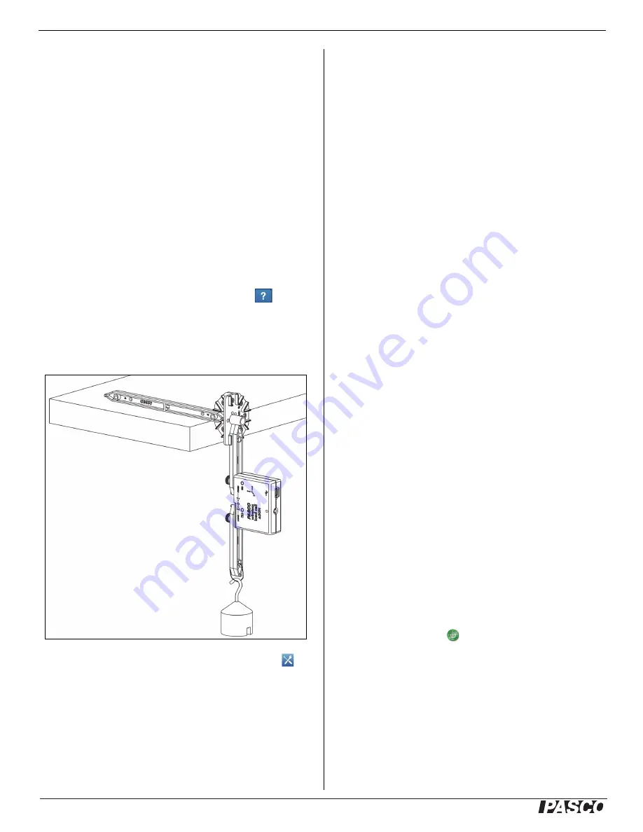
1. Mount the Wireless Load Cell on a calibration fix
-
ture.
2. Click (or press) the Experiment Tools button ( ).
•
The Experiment Tools screen opens.
3. Click Calibrate Sensor.
•
The Calibrate Sensor: Select Measurement screen
opens.
4. Click the Sensor box and click the sensor to be
calibrated.
5. Click the Calibration Type box and click a calibration
type. (For this example, click “2-point”.)
6. Click Next.
•
The Calibrate Sensor Enter Values screen opens.
7. Hang the 1 kilogram mass on the calibration fixture.
8. The gravitational force on the mass is pulling in the
negative direction at -9.8 newtons (N). Under
Calibration Point 1, click the Standard Value box
and enter the known force value (that is, -9.8).
9. Under Calibration Point 1, click Read From Sensor.
•
The value measured by the sensor is transferred to
the Sensor Value box.
10. Remove the 1 kilogram. The net force now is zero N.
11. Under Calibration Point 2, click the Standard Value
box and enter the second known force value (i.e., 0).
12. Under Calibration Point 2, click the Read From
Sensor box.
•
The second value measured by the sensor is
transferred to the Sensor Value box.
13. Click OK.
Using PASCO Capstone for Calibration
See the PASCO Capstone Help for information about
calibrating:
•
In PASCO Capstone, select PASCO Capstone Help
from the Help menu, or press F1.
1. Mount the Wireless Load Cell on a calibration fix
-
ture.
2. Click Calibration ( ) in the Tools palette.
3. Choose the measurement you would like to calibrate
now: Force Measurement.
4. Click Next.
5. Choose the type of calibration you would like to
perform: Two Standards (2 point).
6. Click Next.