


Model No.ME-8236
Appendix:
17
012-13762C
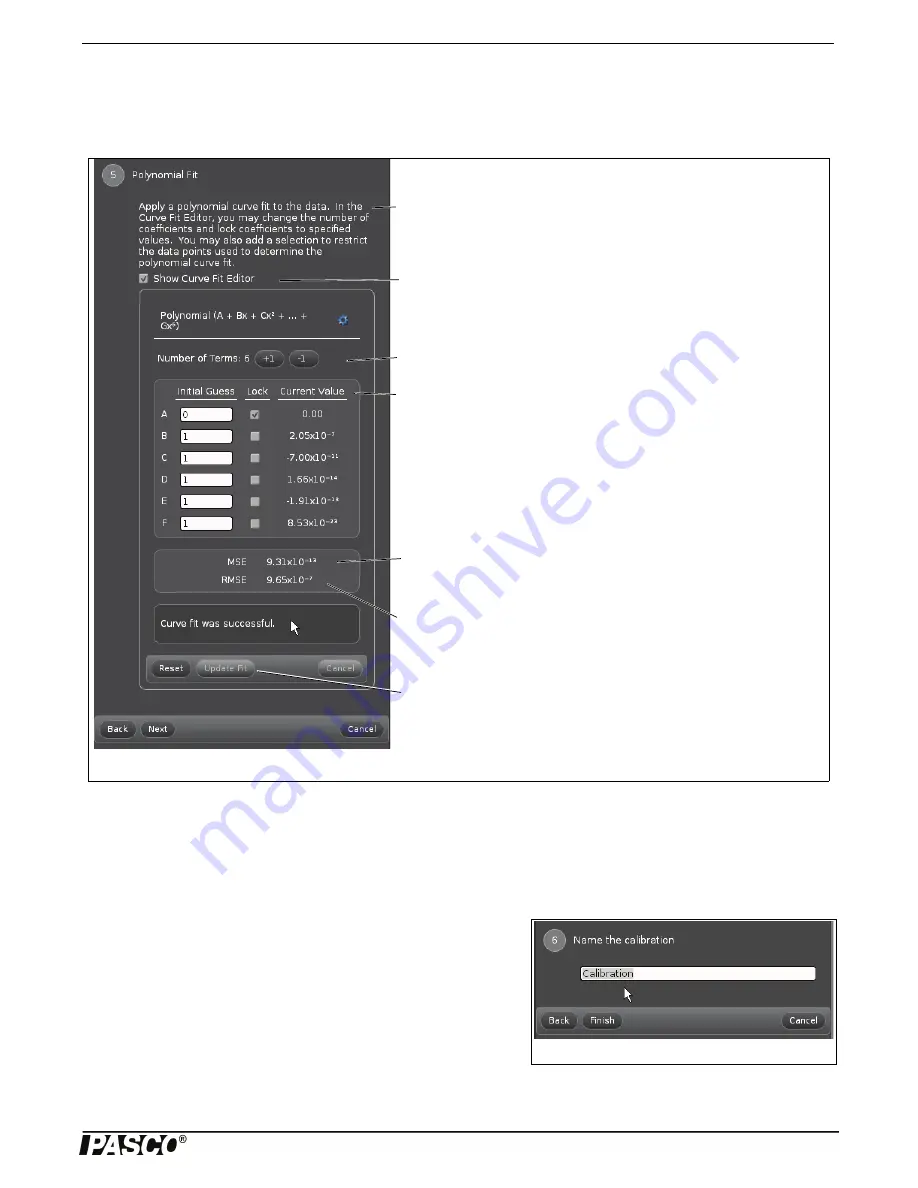
Step Five
•
Click “Next” to open Step Five, “Polynomial Fit”.
NOTE: By default, the “Show Curve Fit Editor” window is open.
•
Note that if the message “Curve fit was successful” is shown, the values of MSE and RMSE will be very small - close to
zero.
NOTE: If the curve fit was not successful, try entering values in the text areas labeled “Initial Guess” in the Curve Fit Editor to
adjust the coefficients. Click “Update Fit” to determine if the coefficients that were entered make a better curve fit.
•
Click “Next” to open Step Six, “Name the calibration”.
Step Six.
•
Type a name for the calibration in the text area. (Example names
might be “Calibration 7000” or “Tension Calibration”.)
Finishing Step
•
Click “Finish” to store the calibration as part of the Capstone file.
NOTE: The “Calibration” window goes back to Step One. When you
click “Next”, the “Choose Calibration Action” window (Step Two) will
show a menu of the stored calibration(s). Click “Use Calibration” to select a specific stored calibration.
Figure: Step Five, Polynomial Fit
Number of Terms
: Click “+1” to increase the number of terms in the polyno-
mial. Click “-1” to decrease the number of terms in the polynomial.
Current Value:
This column shows the values calculated automatically by
the curve fit algorithm. The “A” value is the coefficient for the “zeroth order”
term, the “B” value is the coefficient for the “First order” term, and so on
MSE:
This is an abbreviation for “Mean Squared Error”. It is one way to
quantify the difference between the polynomial fit and the plot of actual data.
Mean Squared Error measures the average of the square of the differences
for each data point.
RMSE
: This is an abbreviation for “Root Mean Squared Error”. Sometimes
called the “standard deviation”, the RMSE is the square root of the MSE.It is
one way to measure the accuracy of the polynomial fit when compared to
the actual data.
Polynomial Fit
: The software automatically applies a polynomial curve fit to
the data.
One option is to click-and-drag a rectangle around a region of the data plot
to restrict the data points that are used to determine the polynomial curve fit.
Show Curve Fit Editor:
On by default.
Update Fit:
Click after values for coefficients are entered to determine if the
coefficients that were entered make a better curve fit.
Figure: Step Six, Name the calibration


