background image

4

PAScar Accessory Track Set (2.2m version)

012-07558A

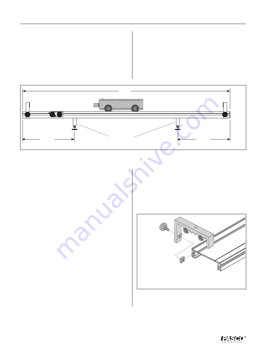
Figure 4: Optimum Position of Leveling Feet

L

1/4 L

1/4 L

Leveling feet

Attach the Adjustable End Stop to the Track

The  Adjustable  End  Stop  can  be  used  at  any  point
on  the  track  as  a  bumper.  Either  the  plunger  bar  on
the  car  or  the  car's  magnetic  bumper  can  be  used  to
rebound  off  the  end  stop  because  the  end  stop
contains  magnets.  The  car  can  also  be  stopped
against  the  end  stop  when  the  Velcro  end  of  the  car
hits  the  Velcro  side  of  the  end  stop.  This  is  useful
for  keeping  the  car  from  rebounding.  There  is  also
a post on top of the end stop to allow a string or
spring  to  be  attached.  Assembly  is  as  follows:

1.

The  Adjustable  End  Stop  Assembly  consists  of
the  end  stop  with  two  magnets  installed,  a  black
plastic  thumb  screw,  and  a  square  nut.

2.

It  is  best  to  install  the  end  stops  in  the  groove
opposite  to  the  side  being  used  for  the  leveling
feet,  so  the  end  stops  can  slide  past  the  feet
without  interference.

3.

Align  the  square  nut  within  the  groove  on  the
desired  side  of  the  Dynamics  Track  (Figure  5).
Locate  and  adjust  the  end  stop  to  the  desired
position  and  tighten  the  thumb  screw  to  secure.

4.    When  storing  the  end  stop,  such  as  when  it  is

not  on  the  track,  keep  it  away  from  computers.
Remember  that  the  end  stop  has  two  strong
magnets  in  it.

Figure 5:  Attaching the Adjustable End Stop

to the Track

the  leveling  screws  up  or  down  to  change  the
height  of  one  end  of  the  track  until  the  car  placed
at rest stays at rest. When the track is level,
tighten  the  lock  nuts  against  the  aluminum  foot.

6. To  take  some  twist  out  of  the  track,  adjust  the

5.

To  level  the  track,  place  a  car  on  the  track  to  see
which  way  it  rolls.    Loosen  the  lock  nuts.    Turn

leveling  screws  on  the  side  of  the  track.

4.

Align  the  square  nut  within  the  groove  on  the
desired  side  of  the  Dynamics  Track.    Slide  the
leveling  foot  down  the  track  to  the  desired  posi-
tion.  To  minimize  the  bow  in  the  track,  place  a
leveling  foot  about  1/4  of  the  track  length  from
each  end  of  the  track  (see  Figure  4).

Summary of Contents for ME-6956

Page 1: ...rack Set 2 2m version Instruction Manual and Experiment Guide for the PASCO scientific Model ME 6956 Includes Teacher s Notes and Typical Experiment Results CAUTIO N M AG NET AVO ID CO NTACT W IT H CO...

Page 2: ......

Page 3: ...ion of Momentum in Collisions 9 Exp 3 Acceleration Down an Incline 11 Exp 4 Simple Harmonic Oscillator 15 Exp 5 Oscillations on an Incline 19 Exp 6 Springs in Series and Parallel 23 Exp 7 Newton s Sec...

Page 4: ...equipment after repair will be paid by PASCO scientific Copyright Notice The PASCO scientific Model ME 6956 PAScar Accessory Track Set 2 2 Meter manual is copy righted and all rights reserved However...

Page 5: ...ack ensures easy setup and accurate alignment with the lowest possible friction and it accomodates most linear motion experiments Features include Adjustable leveling feet Low friction wheel slots kee...

Page 6: ...Stop has a round head screw on the top to allow easy attachment of springs string etc NOTE A small piece of double sided tape is attached to the ends of each storage tube so the tubes may be permanent...

Page 7: ...ing the Pivot Clamp Square nut Bracket washer Short thumb screw Track Long thumb screw 2 Thread two of the long screws through the two holes in the bottom of each alu minum leveling foot The heads of...

Page 8: ...o the end stops can slide past the feet without interference 3 Align the square nut within the groove on the desired side of the Dynamics Track Figure 5 Locate and adjust the end stop to the desired p...

Page 9: ...Assemblies 1 Using a Philips screwdriver loosen the screws and remove the bottom cover plate NOTE A 1 Phillips point screw driver is re quired for removing the thread forming screws on the bottom of...

Page 10: ...t Clamp Assembly 003 05019 1 Pivot clamp 648 04654 1 Long thumb screw 610 183 620 047 1 Short thumb screw 610 181 620 067 1 Washer 615 184 1 Square nut 614 054 1 Plunger bar catch cover 699 04658 1 Pl...

Page 11: ...l speeds of the cars is equal to the ratio of the masses of the cars To simplify this experiment choose the starting point for the cars at rest so that the two cars reach the end of the track simultan...

Page 12: ...OF UNEQUAL MASS Put two mass bars in one car one mass bar in the other Table 1 1 Data Analysis 1 For each of the cases calculate the distances traveled from the starting position to the end of the tr...

Page 13: ...the Velcro pads on the ends of the cars Procedure 1 Level the track by setting a car on the track to see which way it rolls Adjust the leveling feet at the end of the track to raise or lower that end...

Page 14: ...the first car a slow velocity and the second car a faster velocity so that the second car catches the first car Do this for both cases first with the 1M car and then first with the 3M car Part II Com...

Page 15: ...t2 the acceleration can be calculated using Then a plot of acceleration versus sin should give a straight line with a slope equal to the accelera tion due to gravity g Procedure 1 Set up the track as...

Page 16: ...difference between the initial and final positions of the car as given at the top of Table 3 1 3 Calculate the accelerations using the distance and times and record in Table 3 2 4 Measure the hypoten...

Page 17: ...sin slope ______________________ difference _______________ Questions 1 Does your reaction time cause a greater percentage error for higher or lower angles 2 If the mass of the car is doubled how are...

Page 18: ...14 PAScar Accessory Track Set 2 2 Meter 012 07558A Notes...

Page 19: ...lot the force versus the distance the slope of the resulting straight line is equal to k Procedure 1 Use the balance to find the mass of the car Record this value at the top of Table 4 1 2 Level the t...

Page 20: ...5 times and record this data in Table 4 2 Calculations Theoretical Period 1 Using the data in Table 4 1 plot force versus displacement Draw the best fit straight line through the data points and dete...

Page 21: ...cent difference between the measured and theoretical values car alone difference ________________ car with mass difference ________________ Questions 1 Does the period of oscillation increase or decre...

Page 22: ...18 PAScar Accessory Track Set 2 2 Meter 012 07558A Notes...

Page 23: ...t forces to stretch the spring different distances When you plot the force versus distance the slope of the result ing straight line is equal to k Adjustable End Stop Angle of inclination Not included...

Page 24: ...at steps 6 and 7 Calculations TheoreticalPeriod 1 Using the data in Table 5 1 calculate the force caused by the additional mass in the car F mg sin where is the angle of incline Plot force versus disp...

Page 25: ...dividing these times by 3 and record the periods in Table 5 2 Questions 1 Does the period vary as the angle is changed 2 How do the experimental values compare with the theoretical values 3 Does the e...

Page 26: ...22 PAScar Accessory Track Set 2 2 Meter 012 07558A Notes...

Page 27: ...ombined in series or in parallel the spring constants add in different ways One possible way to add two spring constants is keffective k k 2k Another way is which means that Measuring k For a Single S...

Page 28: ...distance and let it go Time 2 oscillations and record the time in Table 6 1 Repeat this measurement at least 5 times using the same initial displacement amplitude 5 Add a second spring in series as sh...

Page 29: ...ta in Table 6 1 calculate the average time for 2 oscillations 2 Calculate the period by dividing these times by 2 and record the periods in Table 6 1 3 Using the periods and the mass of the car calcul...

Page 30: ...h a ruler Observe the resulting acceleration This will be a qualitative measurement VARY THE FORCE Perform the first trial with the spring plunger cocked to the first possible position the least compr...

Page 31: ...is equal to m1 m2 a when friction is ignored To obtain the acceleration the car will be started from rest and the time t it takes for it to travel a certain distance d will be measured Then since d 1...

Page 32: ...l positions of the cart as given in Table 8 1 3 Calculate the accelerations and record in Table 8 2 4 For each case calculate the total mass multiplied by the acceleration and record in Table 8 2 5 Fo...

Page 33: ...sulting straight line is equal to k The gravitational potential energy gained by a car as it climbs an incline is given by potential energy mgh where m is the mass of the car g is the acceleration due...

Page 34: ...g feet 7 Remove the string from the car and cock the spring plunger to its maximum compression position Place the car against the end stop Measure the distance the spring plunger is compressed and rec...

Page 35: ...ment Draw the best fit straight line through the data points and determine the slope of the line The slope is equal to the effective spring constant k k ______________ 2 Calculate the spring potential...

Page 36: ...32 PAScar Accessory Track Set 2 2 Meter 012 07558A Notes...

Page 37: ...ction initially and observe Add a mass bar to one car and repeat Experiment 13 Newton s Second Law III Repeat Experiment 8 with the track inclined so the pulley is on the high end and the car accelera...

Page 38: ...apart Push the left cart into the middle cart which in turn will collide with the PAScar The carts will all stick together Note the resulting final velocity of the carts Experiment 19 Rocket Staging U...

Page 39: ...ar it is on there is no difference when the cars are separated Teacher s Guide Experiment 1 Conservation of Energy in Explosions Experiment 2 Conservation of Momentum in Collisions NOTE Without some m...

Page 40: ...Our value 3 3 low Experiment 3 Acceleration Down an Incline Answers to Questions 1 Assuming that reaction time is relatively con stant the percent error due to reaction time would be greater for shor...

Page 41: ...d be less than 2 and it is not unusual to obtain errors of less than 0 5 Answers to Questions 1 The period of oscillation increases with mass The more massive car oscillates slower 2 The period is not...

Page 42: ...as the spring is ex tended at greater angles the force constant is not constant The contribution due to friction also changes with angle 2 The experimental results should agree with theory to within...

Page 43: ...d of the track when the springs are in series Notes on Calculations The two springs used for this experiment had spring constants of 1 53 and 1 60 Actual spring constants may vary from spring to sprin...

Page 44: ...total mass times acceleration The difference between the two is the force of friction 3 The hanging mass is accelerating at the same rate as the car so both the hanging mass and the car s mass must b...

Page 45: ...you won t lose valuable data If possible have the apparatus within reach when calling This makes descriptions of indi vidual parts much easier If your problem relates to the instruction manual note P...

Page 46: ......

Reviews: