www.parweld.co.uk
12
ACCESSORIES
6.1.3 Feeding Wire Electrode
1. When triggering, the electrode and drive mechanism are
electrically “LIVE” relative to work and ground and remain
“LIVE” several seconds after the torch trigger is released.
WarnInG
When using an open arc process, it is necessary to use correct
eye, head, and body protection.
2. Position wire over joint. The end of the wire may be lightly
touching the work.
3. Lower welding helmet, operate torch trigger, and begin welding.
Hold the torch so the contact tip to work distance is about 3/8”
(10 mm).
4. To stop welding, release the torch trigger and then pull the torch
away from the work after the arc goes out.
5. When no more welding is to be done, close valve on gas
cylinder (if used), momentarily operate torch trigger to release
gas pressure and turn off the machine.
6.1.4 Optimising Weld Parameters (Manual Mode)
nOte these settings are guidelines only. Material and wire
type, joint design, fit up, position, shielding gas, etc. Affect
settings. produce test welds to be sure they comply to
specifications.
Material thickness determines weld parameters.
1. Convert Material Thickness to Amperage (A) (0.025mm = 1
Amp) 3.2mm = 125 A
2. Select Wire Size
Amperage Range
Wire Size
40 - 145 A
0.8 mm
50 - 180 A
1.0 mm
3. Select Wire Speed (Amperage)
Wire Size
Feed speed
0.8 mm
0.05m/min per Amp
1.0 mm
0.04m/min per Amp
So based on 3.2 mm material thickness amperage should be 125A if
using 1.0mm wire then the wire feed speed should be
0.04 X 125= 5m/min
Wire speed (amperage) controls weld penetration
4. Select Voltage. Voltage controls height and width of weld bead.
Low Voltage: wire stubs into work
High Voltage: arc is unstable (spatter)
Set voltage midway between high/low voltages.
And then fine tune accordingly
6.1.5 Optimising Weld Parameter (Synergic Mode).
In synergic mode you may wish to trim the voltage (4) to optimize
the welding process, you can rotate the voltage control left or right to
decrease or increase the preset welding voltage. You can also adjust
the inductance (11) to change the hardness of the arc.
6.1.6 Burn Back
The amount of wire stick out at the end of the torch after welding can
be adjusted by using the burn back control in the help menu.
6.1.7 Pre and Post Gas Setting
The amount of Pre and post Gas can be set using the
gas function in the Help menu
6.1.8 Aluminium Welding
1. Change inlet guide to a sleeved one to protect the wire.
Remove the MIG torch, remove the securing screw to release
the brass guide, and push the guide out through the machine
connection block.
2. Slide the sleeved inlet guide onto the end of the liner in the
torch and push back into the machine.
3. Replace the small piece of steel liner assembled to the left side
of the wire feed unit with a piece of Teflon liner.
6.1.9 2T - 4T trigger
IN 2T mode, you press and hold in the trigger to weld and release at
the end of the weld. In 4T mode press an release the trigger to start.
Press and release again to stop.
6.2 MMA Welding
6.2.1
Unthread the MIG welding wire from the MIG Torch and
remove the spool or secure the wire to prevent un-spooling.
6.2.2 Torch and Work Lead Connections
Connect the electrode lead to the positive terminal and the work lead
to the negative terminal.
6.2.3 Operation
Select the operating mode on the front panel to MMA (10)
Using the optional electrode holder, clamp a welding electrode in the
holder and adjust the welding amperage on the power source front
panel so that it is approximately 40A per mm diameter of electrode
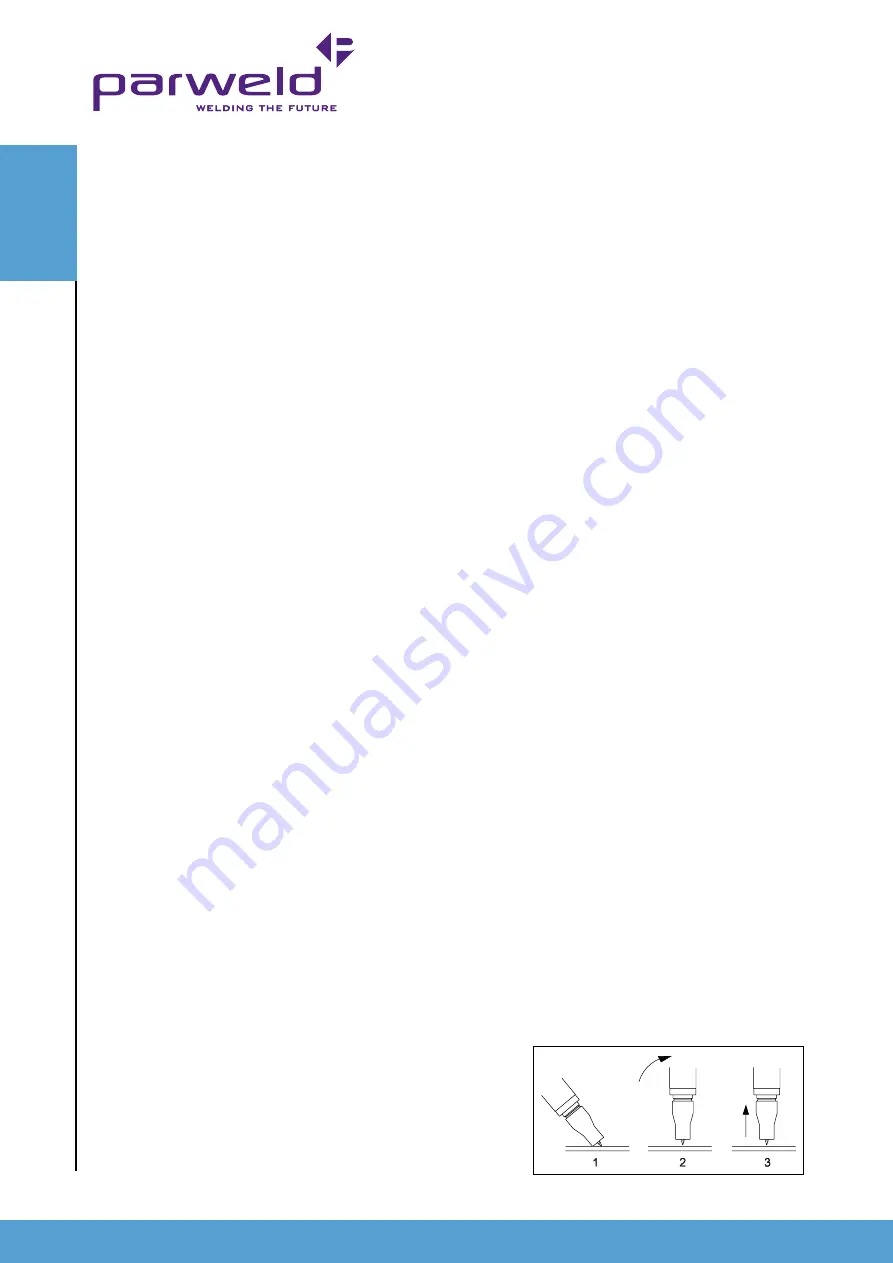
e.g. 3.2mm electrode requires 3.2x 40A= 128A . Strike the arc by
stroking the electrode on the work piece. And lift away when you
wish to break the arc.
6.2.4 Arc Force
The Arc Force can be adjusted between 0 and 10 using the control
knob (12). The V meter will display the OCV or welding voltage after
adjustment
6.3 TIG Welding Operation
to begin tIG welding operation:
NB: this machine only operates in DC Lift TIG mode and therefore
NOT suitable for TIG welding aluminium.
1. Unthread the MIG welding wire from the MIG Torch and remove
the spool or secure the wire to prevent un-spooling.
2. Attach the Negative power outlet (14)
3. Connect the Work Return Lead to the + Power Outlet (13).
4. Connect the Gas Hose & Regulator to a suitable gas source
(for TIG operation this will be Pure Argon and may differ to what
was being used for the MIG process)
5. Use the function selection control (10) to select the TIG function
6. Adjust the Amperage control (11) to the desired power output


