34
3.
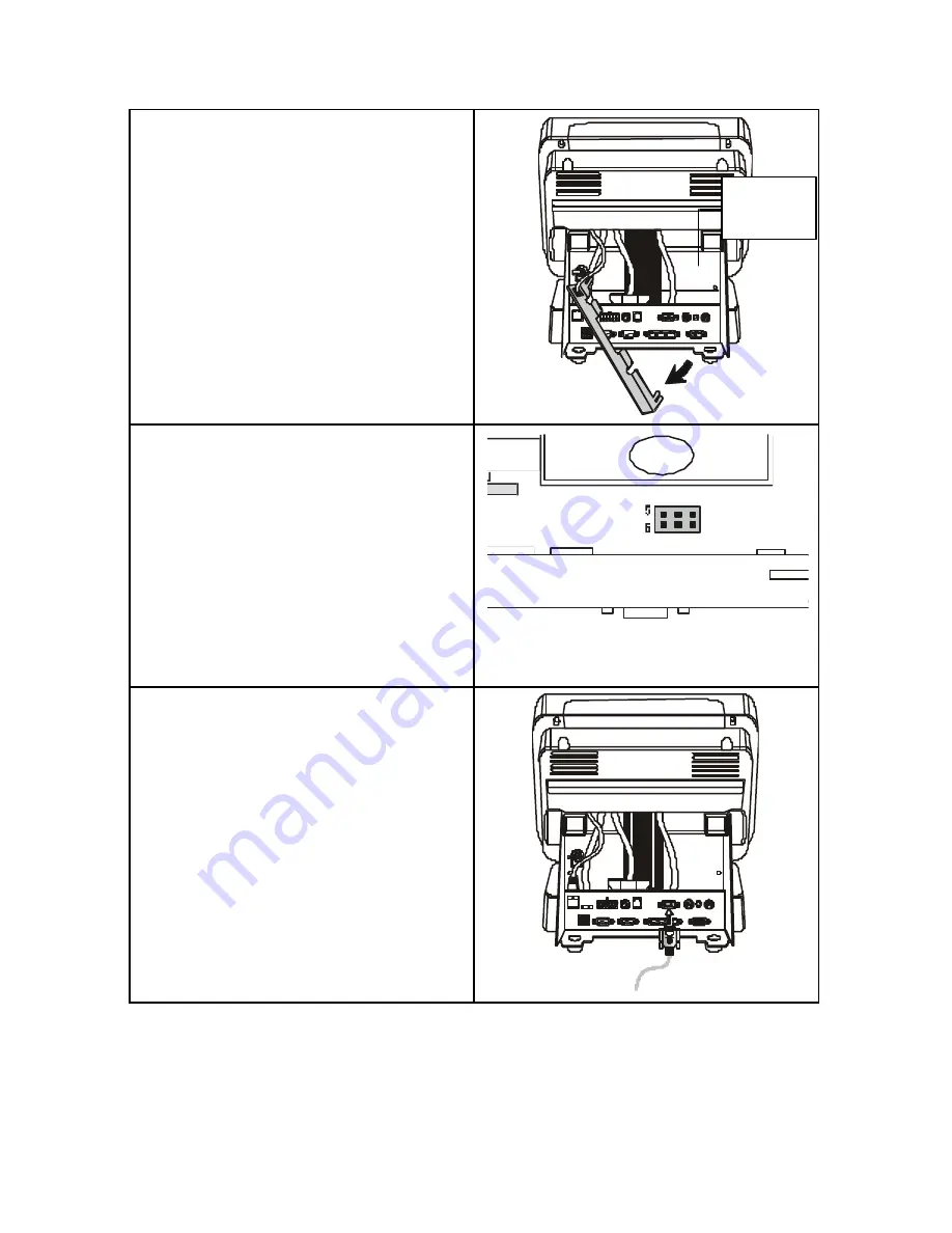
Move the PCB board cover to the
side and locate the PCB board.
4.
Short pins 5-6 (DC 12V) of the
Power PCB jumper JP1 (see
Appendix C for the jumper
location). Replace the PCB board
cover and secure it with the two
screws:
P11
JP1
1
2
5.
Connect the display cable of the
Customer Pole Display to COM 3:
Replace the Rear Cover.
PCB
board


