


Replacing Parts
75
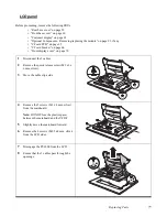
Mainboard
Before proceeding, remove the following FRUs:
• “Rear base cover” on page 59
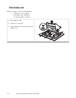
• “Front base cover” on page 60
• “Customer display” on page 62
• “Optional Components - Removing/replacing the module” on page 91, if any
• “CF card PCB” on page 65
• “CF card bracket” on page 66
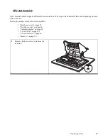
• “CPU and heatsink” on page 67
• “Inverter shield” on page 68
• “Inverter” on page 69
• “Memory” on page 70
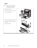
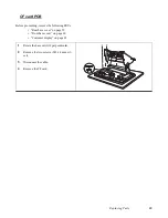
• “Video PCB” on page 71
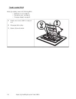
• “Touch control PCB” on page 74
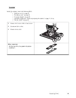
1
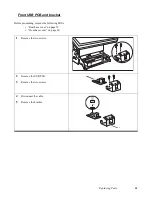
Disconnect the 5 cables.
2
Remove the 5 screws (M3 x 4 mm, silver).
3
Remove the mainboard.
Summary of Contents for PT-6900
Page 1: ...PT 6900 Service Manual...
Page 2: ......
Page 7: ...v List of Parts FRUs 92 Display Parts and Cables 94...
Page 8: ...vi...
Page 10: ...viii...
Page 16: ...6 Getting Started...
Page 38: ...28 BIOS Setup Utility...
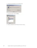
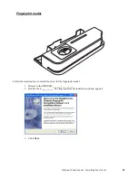
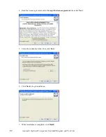
Page 52: ...42 Installing Drivers and Software 5 When installation is completed click Finish...
Page 66: ...56 Locating the Problem...
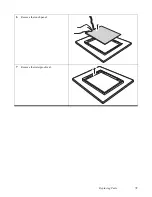
Page 83: ...Replacing Parts 73 6 Remove the touch panel 7 Remove the waterproof seal...
Page 88: ...78 Replacing Field Replaceable Units FRUs...
Page 96: ...86 Appendix Optional Components Exploded Diagram and Parts List...
Page 106: ...96 Appendix Optional Components Exploded Diagram and Parts List...