


7
C
HAPTER
2
BIOS S
ETUP
U
TILITY
The BIOS (Basic Input and Output System) Setup Utility displays the system's configuration status and provides
options to set system parameters. The parameters are stored in battery-backed-up CMOS RAM that saves this informa-
tion even when the power is turned off. When the system is turned back on, the system is configured with the values
found in CMOS.The following topics are described in this chapter.
• “About the Setup Utility”
• “Entering the Setup Utility” on page 8
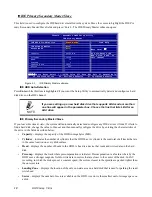
• “Standard CMOS features” on page 9
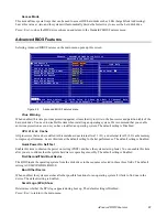
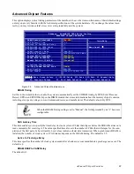
• “Advanced BIOS Features ” on page 11
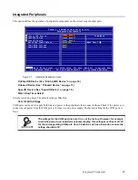
• “Integrated Peripherals ” on page 15
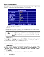
• “Power Management Setup” on page 20
• “PnP/PCI Configurations” on page 22
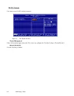
• “PC Health Status” on page 24
• “Frequency/Voltage Control” on page 25
• “Other BIOS Options” on page 26
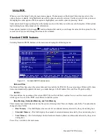
About the Setup Utility
The BIOS Setup Utility enables you to configure the following items:
•
Hard drives, diskette drives, and peripherals
•
Video display type and display options
•
Password protection from unauthorized use
•
Power management features
This Setup Utility should be used for the following:
•
When changing the system configuration
•
When a configuration error is detected and you are prompted to make changes to the Setup Utility
•
When trying to resolve IRQ conflicts
•
When making changes to the Power Management configuration
•
When changing the User or Supervisor password
TIP
If you have made settings that you do not want to save, use the "Exit Without
Saving" item and press Y to discard any changes you have made.
Summary of Contents for PT-6900
Page 1: ...PT 6900 Service Manual...
Page 2: ......
Page 7: ...v List of Parts FRUs 92 Display Parts and Cables 94...
Page 8: ...vi...
Page 10: ...viii...
Page 16: ...6 Getting Started...
Page 38: ...28 BIOS Setup Utility...
Page 52: ...42 Installing Drivers and Software 5 When installation is completed click Finish...
Page 66: ...56 Locating the Problem...
Page 83: ...Replacing Parts 73 6 Remove the touch panel 7 Remove the waterproof seal...
Page 88: ...78 Replacing Field Replaceable Units FRUs...
Page 96: ...86 Appendix Optional Components Exploded Diagram and Parts List...
Page 106: ...96 Appendix Optional Components Exploded Diagram and Parts List...