


18
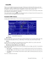
BIOS Setup Utility
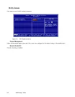
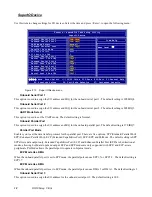
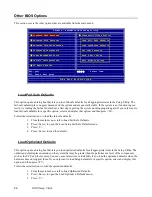
SuperIO Device
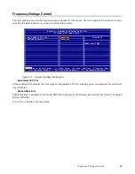
Use this item to change settings for I/O devices. Select the item and press <Enter> to open the following menu:
Figure 2.10
Super IO Device menu
Onboard Serial Port 1
This option is used to assign the I/O address and IRQ for the onboard serial port 1. The default setting is 3F8/IRQ4.
Onboard Serial Port 2
This option is used to assign the I/O address and IRQ for the onboard serial port 2. The default setting is 2F8/IRQ3.
UART Mode Select
This option is used to set the UART mode. The default setting is Normal.
Onboard Parallel Port
This option is used to assign the I/O address and IRQ for the onboard parallel port. The default setting is 378/IRQ7.
Parallel Port Mode
Enables you to set the data transfer protocol for the parallel port. There are five options: SPP (Standard Parallel Port),
EPP (Enhanced Parallel Port), ECP (Extended Capabilities Port), ECP+EPP, and PntMode. The default setting is SPP.
SPP allows data output only. Extended Capabilities Port (ECP) and Enhanced Parallel Port (EPP) are bi-directional
modes, allowing both data input and output. ECP and EPP modes are only supported with EPP- and ECP-aware
peripherals. PntMode allows the parallel port to operate in bipoloar mode.
ECP Mode Use DMA
When the onboard parallel port is set to EPP mode, the parallel port can use EPP1.7 or EPP1.9. The default setting is
EPP1.7.
ECP Mode Use DMA
When the onboard parallel port is set to ECP mode, the parallel port can use DMA 3 or DMA 1. The default setting is 3.
Onboard Serial Port 3
This option is used to assign the I/O address for the onboard serial port 3. The default setting is 3E8.
P
hoenix – AwardBIOS CMOS Setup Utility
SuperIO Device
Onboard Serial Port 1
[3F8/IRQ4]
Onboard Serial Port 2
[2F8/IRQ3]
Item Help
UART Mode Select
[Normal]
Onboard Parallel Port
[378/IRQ7]
Menu Level
``
Parallel Port Mode
[SPP]
x EPP Mode Select
EPP1.7
x ECP Mode Use DMA
3
Onboard Serial Port 3
[3E8]
Serial Port 3 Use IRQ
[IRQ3]
Onboard Serial Port 4
[2E8]
Serial Port 4 Use IRQ
[IRQ4]
Onboard Serial Port 5
[4F8]
Serial Port 5 Use IRQ
[IRQ5]
Onboard Serial Port 6
[4E8]
Serial Port 6 Use IRQ
[IRQ7]
ÇÈÅÆ
:Move Enter:Select +/-/PU/PD:Value F10:Save ESC:Exit F1:General Help
F5: Previous Values F6: Fail-Safe Defaults F7: Optimized Defaults
Summary of Contents for PT-6900
Page 1: ...PT 6900 Service Manual...
Page 2: ......
Page 7: ...v List of Parts FRUs 92 Display Parts and Cables 94...
Page 8: ...vi...
Page 10: ...viii...
Page 16: ...6 Getting Started...
Page 38: ...28 BIOS Setup Utility...
Page 52: ...42 Installing Drivers and Software 5 When installation is completed click Finish...
Page 66: ...56 Locating the Problem...
Page 83: ...Replacing Parts 73 6 Remove the touch panel 7 Remove the waterproof seal...
Page 88: ...78 Replacing Field Replaceable Units FRUs...
Page 96: ...86 Appendix Optional Components Exploded Diagram and Parts List...
Page 106: ...96 Appendix Optional Components Exploded Diagram and Parts List...