background image


a)  Ram advances   

and retracts when handle is pumped ..


Removing Air From System. 


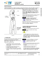
1.  Position the tool upside-down in a vice with the pump handle in 

the open  position. 


2.  Unscrew the fixed main handle from the body, then remove the 

reservoir 


end cap.


3.  Pump the moving handle and press the release button in at the 

same time, this will open hydraulic oil chambers and will allow the 
air bubbles to rise out of the tool system into the oil reservoir. The 
moving handle should be pumped for a minimum of 10 operations. 


4.  It is advised to leave tool upside down with end cap off for a further 

10 to 15 minutes, this will allow any air bubbles that are trapped in 

reservoir to rise and escape. 


5.  Top up hydraulic fluid if required , pump the moving handle 

 so  the

  ram advances but does not come under pressure. Now 

 press release trigger and close moving handle.  This will 

 release oil back into the reservoir together with  any trapped air bubbles.  


6.  After all air bubbles have been released, lightly squeeze the top 

of the rubber reservoir so the oil is slightly over flowing and insert 

the filler cap.  Any excess oil should be wiped from tool before use.


Oil Refilling:


Check oil level periodically and top up if required. 


 OIL TYPE :  TELLUS GRADE 15  ONLY.  


ISSUE: 10/13 ORIGINAL
PAGE 11

b) Ram does not move when handle is pumped.

c) Unit does not reach pressure.

Air in hydraulic system

( repeat this process several times to ensure that all air bubbles


have been removed ).

Summary of Contents for PHCT240-Kit

Page 1: ...Tool PHCT240 Kit ATTENTION Safe Operation Maintenance Instructions must be followed PARTEX MARKING SYSTEMS UK LTD 61 64 Station Road Coleshill Birmingham B46 1JT Phone 01675 463670 Fax 01675 463520 Em...

Page 2: ...Contents 1 Safety Instructions 2 Product Description 3 Maintenance 4 Operating Instructions 5 6 7 Dies 8 Compression Diagram 9 Trouble Shooting 10 11 List of Components 12 Diagram of Components 13 IS...

Page 3: ...low ALL instructions to ensure safety WARNING Keep hands away from the compression area while operating this product This product is fully insulated Proper equipment should be used to avoid electrical...

Page 4: ...d for easy die changes and removal of connectors Built in pressure relief valve for constant compression Adjustable ram stroke 10 15 mm Spring loaded pump handle allows one handed operation Small hand...

Page 5: ...the tool into contact with water or solvents Do NOT store this product in places with high temperatures high humidity or direct sunlight Hydraulic fluid temperatures over 65 C might cause damage to c...

Page 6: ...oint During operation 1 Keep tool clean and free from debris Excessive dirt debris can contribute to the breakdown of the hydraulic system Regular checks during operation cycle should be made for fore...

Page 7: ...ool When the ram and bottom die holder return to the starting position the tool is ready to be operated 2 Pull back the latch to open the head the yoke will now spring open 3 Slide the dies into the t...

Page 8: ...will rapidly advance When the lower die makes contact with the terminal connector the tool will then slowly press the terminal until full compression is reached 4 Continue pumping until both dies are...

Page 9: ...16 6 8 2 85 12 25 to 35 A CU25 8 35 3 5 9 B CU35 9 4 4 9 50 to 70 A CU50 11 35 4 8 9 B CU70 13 8 6 05 9 95 to 120 A CU95 16 17 6 9 9 B CU120 18 05 7 6 9 150 A CU150 20 15 8 55 6 185 A CU185 22 15 9 35...

Page 10: ...Compression Diagrams Butt connectors Direction of Compression Single compression headed die Terminal Connectors Direction of Compression Single Compression headed dies ISSUE 10 13 ORIGINAL PAGE 9...

Page 11: ...ed A Deformed tool head runner or die holder B Head die runners dirty or not lubricated Piston unable to advance or retract during operation A Piston damaged or distored B Die runners damaged Do NOT a...

Page 12: ...bubbles that are trapped in reservoir to rise and escape 5 Top up hydraulic fluid if required pump the moving handle so the ram advances but does not come under pressure Now press release trigger and...

Page 13: ...LDING BAND 1 14 COMPRESSION SPRING 3 48 PIN 1 15 COMPRESSION SPRING 2 49 DUST SEAL 1 16 COMPRESSION SPRING 1 50 COMPRESSION SPRING 1 17 PUSH IN FASTENER 5 51 SCREW 1 18 OIL SCREEN 2 52 MAIN PISTON 1 1...

Page 14: ...Parts Drawing ISSUE 10 13 ORIGINAL PAGE 13...

Reviews: