


©2012 Tyco Electronics Corporation, a TE Connectivity Ltd. Company
All Rights Reserved
*Trademark
TE Connectivity, TE connectivity (logo), and TE (logo) are trademarks. Other logos, product and/or Company names may be trademarks of their respective owners.
1 of 6
Instruction Sheet
TOOLING ASSISTANCE CENTER 1-800-722-1111
PRODUCT INFORMATION 1-800-522-6752
This controlled document is subject to change.
For latest revision and Regional Customer Service,
visit our website at www.te.com
LOC B
408-1254
Terminal and Splice
Crimping Tools
69339, 69354-1, and 69355
11 JUN 12 Rev D
PROPER USE GUIDELINES
Cumulative Trauma Disorders can result from the prolonged use of manually powered hand tools. Hand tools are intended for occasional use
and low volume applications. A wide selection of powered application equipment for extended-use, production operations is available.
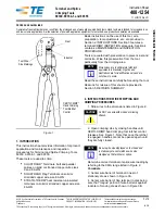
Figure 1
1. INTRODUCTION
This instruction sheet provides information for product
application and maintenance and inspection
procedures for Terminal and Splice Crimping Tools
69339, 69354-1, and 69355.
These tools are used to crimp:
•
SOLISTRAND* Terminals, butt and parallel
splices on solid or stranded copper wire sizes
6 and 8 AWG
•
SOLISTRAND Flag Terminals on solid or
stranded copper wire size 8 AWG
•
STRATO-THERM* heat resistant uninsulated
terminals on solid or stranded copper wire size
8 AWG
Basic instructions on the use of this tool, wire
preparation, tool adjustments, etc. are provided in
Section 2, INSTRUCTIONS. Section 3 features a
terminal CRIMP INSPECTION procedure. Section 4
contains a MAINTENANCE and INSPECTION
PROCEDURE.
Tools are coated with preservative to prevent rust and
corrosion. Wipe this preservative from the tool,
particularly from the crimping area.
Read these instructions carefully before using the tool.
Reasons for reissue of this sheet are provided in
Section 5, REVISION SUMMARY.
2. INSTRUCTIONS FOR WIRE STRIPPING AND
CRIMPING PROCEDURES
1. Strip wires to the dimensions listed in Figure 2.
2. Open crimping dies by closing handles until
CERTI-CRIMP hand crimping tool ratchet control
releases. See Figure 1. Note that once the ratchet
is engaged, handles cannot be opened again until
they are fully closed.
Determine correct terminal or splice wire loading by
referring to the CMA range listed in Figure 2.
Terminals
3. Center wire barrel of terminal in nest of
stationary die as shown in Figure 3A.
4. Center wire barrel of flag terminal in dies being
sure that “tongue” portion of wire barrel is against
indenter of moving die as shown in Figure 3B.
Nest
Indenter
Tool Wire
Size Markings
CERTI-CRIMP*
Hand Crimping
Tool Ratchet
Control
NOTE
Dimensions are in millimeters [with inch
equivalents in brackets]. Figures and
illustrations are for identification only and are
not drawn to scale.
CAUTION
Do NOT use wire with nicked or missing
strands.
NOTE
Be sure wire size displayed on tool head and
in stationary die nest matches wire size
stamped on the terminal or splice.
i
i
O
R
IG
INAL
INST
RUCTIONS


