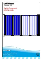


PLC Usage Explained
Menu/Ok
SR2 B121BD
1
2
Q1
1
2
Q2
1
2
Q3
1
2
Q4
+
-
I1
I2 I3 I4 IB
ID
IC
IE
24VDC
24VDC
24VDC
Analog or
IB....IE
Inputs I1...I4
Outputs
Q1...Q4 : Relay 8A
Menu/Ok
SR2 B121BD
1
2
Q1
1
2
Q2
1
2
Q3
1
2
Q4
+
-
I1
I2 I3 I4 IB
ID
IC
IE
24VDC
24VDC
24VDC
Analog or
IB....IE
Inputs I1...I4
Outputs
Q1...Q4 : Relay 8A
1.
2.
4.
3.
Memory card
slot
Outputs
Inputs
Power
Inputs
Left
Right
Up
Down
Menu/Ok
LCD Screen
1. Shows where key components are located on the Programmable Logic Control.
2. To program the PLC using the instructions below the only tool you need to use is one finger making
sure to press the correct buttons in the correct sequence.
3. To upload a new program via a PLC memory chip open the memory card slot flap and move to step
4.
4. Now follow the instructions below very carefully. When asked to insert the chip, hold the chip so that
the memory word is the correct way up and at the top. Then with even force push forward into the slot
so its sits flush to the PLC housing. Once inserted leave it in place until it states “download complete”.
After all steps have been completed you MUST replace the slot cover.
Steps to upload a new program from Eprom:
1.
Press menu / ok button once.(Green Button)
2.
Scroll down to run / stop (flashing).
3.
Insert New PLC chip
4.
Press menu / ok button to stop program.
5.
Press menu / ok again.
6.
Scroll down to transfer (flashing).
7.
Press menu / ok button once.
8.
The screen will display transfer:
Zelio > memory
Memory > Zelio
9.
Scroll down to
Memory > Zelio
.
NOTE! this is very important to select the right path as you may
risk
wiping the memory!!
10.
Press menu / ok button.(Green Button)
11.
When downloaded TRANSFER OK / STOP LD will be displayed.
12.
Press menu / ok button.
13.
Scroll up to run / stop (flashing).
14.
Press menu / ok button.(Green Button)
15.
Screen will display RUN PROG.
YES (with nonvolat) (flashing)
NO
16.
Make sure “YES” is selected then press menu / ok button.(Green Button)
17.
The chip has now been downloaded.
18.
STOP CIRCUIT BROKEN may now appear on the screen because the cabinet door is open.
19.
Now replace the memory slot cover!.
(Green Button)
(Green Button)
(Green Button)
(Green Button)
!
Green Button
Menu/Ok
SR2 B121BD
1
2
Q1
1
2
Q2
1
2
Q3
1
2
Q4
+
-
I1
I2 I3 I4 IB
ID
IC
IE
24VDC
24VDC
24VDC
Analog or
IB....IE
Inputs I1...I4
Outputs
Q1...Q4 : Relay 8A
Menu/Ok
SR2 B121BD
1
2
Q1
1
2
Q2
1
2
Q3
1
2
Q4
+
-
I1
I2 I3 I4 IB
ID
IC
IE
24VDC
24VDC
24VDC
Analog or
IB....IE
Inputs I1...I4
Outputs
Q1...Q4 : Relay 8A
Te
le
m
sgdsddvsvd
dsydsdsgdysd
ysgdsygys
ydsydgsygdsy
GL
SO
Summary of Contents for PF9500A
Page 4: ...Technical Drawing Example 3 PF9500A ...
Page 20: ...Wiring Diagram Master PF9500A ...
Page 21: ...Wiring Diagram Master PF9500A ...
Page 22: ......
Page 24: ...Loop Guide ...
Page 25: ...Loop Guide ...
Page 26: ...Loop Guide ...
Page 27: ...Loop Guide ...
Page 28: ...Loop Guide ...
Page 29: ...Loop Guide ...
Page 30: ...Master Slave Wiring Info ...


