background image

13

Parker Hannifi n Corporation

Velcon  Filtration Division

Colorado Springs, CO 80907 USA

Velcon Filtration Division

Filter Vessel Installation & Operation Manual

VEL2199 0414

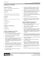
10.  Screw the nut at the end of the tie rod down 

against the mounting adapter while preventing the 
tie rod from turning.  

11.  Tighten the nut to 5 foot pounds of torque.  

12.  Install the other tie rods so that they extend out 

from the mounting adapters the same length as 
the fi rst rod.

SEPARATOR WITH SEAL NUT (WITH OR WITHOUT 
SPIDER PLATE):

1.  Screw a nut on one end of the tie rod to about 2” 

from the end. (See note below.)  

2.  Slide a lock washer up against the nut on the 

shortened side of the tie rod.  

3.  Slide a mounting adapter (on vessels with integral 

cast-in or welded-in mounting adapters, no ad-
ditional adapter is required) on the short side of the 
tie rod with the cartridge seal side facing the nut 
and washer.

4.  While holding the mounting adapter on the end of 

the rod, screw the short end of the tie rod into the 
tie rod bar on the vessel.  Screw in about one inch.  

5.  Install a separator over the tie rod and into place 

on the mounting adapter so the tie rod extends 
from the end seal cap tie rod hole.  

6.  On double open ended separators, place an end 

seal plate on the top or end of the separator, with 
the tie rod extending out from the end seal plate tie 
rod hole.

7.  Adjust the tie rod by screwing it in or out until the 

amount extending beyond the end seal plate is 
one (1) inch.

8.  Remove the cartridges, spacers, and seal plates. 

9.  Screw the nut at the end of the tie rod down 

against the mounting adapter while preventing the 
tie rod from turning.  

10.  Tighten the nut to 5 foot pounds of torque.  

11.  Install the other tie rods so that they extend out 

from the mounting adapters the same length as 
the fi rst rod.

NOTE

1.  In AHM06xxx, AVM06xxx, HM06xxx, 

and VM06xxx Aquacon® vessels, the 
nut should be screwed on to the tie 
rod to about 4” from the end instead 
of 2”.

2.  In three stage HVM-xxxx fi lter/sepa-

rator vessels, the nut on the separa-
tor tie rods should be screwed on to 
the tie rod to about 4” from the end 
instead of 2”.

Summary of Contents for Velcon VF Series

Page 1: ...il 2014 Standard Filter Vessel Installation and Operation Manual VF HF Parker Hannifin Corporation Velcon Filtration Division 1210 Garden of the Gods Road Colorado Springs CO 80907 1 719 531 5855 Phon...

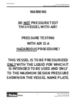
Page 2: ...lter Vessel Installation Operation Manual VEL2199 0414 WARNING DO NOT PRESSURE TEST THIS VESSEL WITH AIR PRESSURE TESTING WITH AIR IS A HAZARDOUS PROCEDURE THIS VESSEL IS TO BE PRESSURIZED ONLY WITH T...

Page 3: ...osures 11 Installing Tie Rods 12 Appendix A Pleated Media Filter Cartridges 16 17 B F0 6xxA3 FOH 6xxA1 EI1590 Qualified Filter Cartriges 18 19 C VF Series Vertical Filter Vessels 20 21 D Assembly Torq...

Page 4: ...4 Parker Hannifin Corporation Velcon Filtration Division Colorado Springs CO 80907 USA Velcon Filtration Division Filter Vessel Installation Operation Manual VEL2199 0414...

Page 5: ...COVER TO ENSURE STABILITY OF THE FILTER 3 Bolt the filter to a stable base 4 Carefully install correct gaskets on the inlet and outlet connections and connect to the inlet and outlet piping 5 Connect...

Page 6: ...Turn the handle the other way 90 or 180 depending on the type of valve and record the pressure reading C Subtract the lower reading from the higher reading to determine differential pressure The high...

Page 7: ...ghten nuts on tie rods until the rubber wash ers begin to curl Do not over torque K Check the cover gasket for alignment re place the cover and secure tightly The Filter is now ready for the start up...

Page 8: ...8 Parker Hannifin Corporation Velcon Filtration Division Colorado Springs CO 80907 USA Velcon Filtration Division Filter Vessel Installation Operation Manual VEL2199 0414...

Page 9: ...9 Parker Hannifin Corporation Velcon Filtration Division Colorado Springs CO 80907 USA Velcon Filtration Division Filter Vessel Installation Operation Manual VEL2199 0414 Installation Instructions...

Page 10: ...er to the threaded clips on the vessel walls using the nut and lockwasher Adjust the spider clip nuts so the spider lies flat on the ends of the cartridges Install the washer and nut over the ends of...

Page 11: ...able One lists guideline torque values for lubricated bolts for common sizes used for vessel closures Always use lubricated bolts as this reduces the required torque improves torque accuracy and retar...

Page 12: ...p or end of the cartridge or cartridge stack with the tie rod ex tending out from the end seal plate tie rod hole 8 Adjust the tie rod by screwing it in or out until the amount extending beyond the en...

Page 13: ...screw the short end of the tie rod into the tie rod bar on the vessel Screw in about one inch 5 Install a separator over the tie rod and into place on the mounting adapter so the tie rod extends from...

Page 14: ...14 Parker Hannifin Corporation Velcon Filtration Division Colorado Springs CO 80907 USA Velcon Filtration Division Filter Vessel Installation Operation Manual VEL2199 0414...

Page 15: ...15 Parker Hannifin Corporation Velcon Filtration Division Colorado Springs CO 80907 USA Velcon Filtration Division Filter Vessel Installation Operation Manual VEL2199 0414 Appendix Accessories...

Page 16: ...from most industrial fluids Corrugated Media Prevents pleat pinch off assuring all filtration media is utilized Buna N Gaskets The best general gasket material available assures positive seal in most...

Page 17: ...44PLF5M 5 Yes FO 644PLF10M 10 Yes FO 644PLF15M 15 Yes FO 644PLF25M 25 Yes Model Dim Nominal Micron Rating Protec tive Outer Wrap FO 644PLF1 4TB 6 x 44 Threaded Base Yes FO 644PLF1 2TB Yes FO 644PLF1TB...

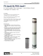
Page 18: ...tions and Qualification Procedures for Aviation Fuel Microfilters Product Features Large Surface Area Allows high flow rate with low initial pressure drop and maximum contaminant holding capacity Resi...

Page 19: ...614A3TB 6 x 141 2 x 31 2 ID NO 3 47 FO 629A3 6 x 29 x 31 2 ID YES 3 111 FO 629A3TB 6 x 29 x 31 2 ID YES 3 105 FO 644A3 6 x 44 x 31 2 ID YES 3 171 FO 644A3TB 6 x 44 x 31 2 ID YES 3 165 FO 656A3 6 x 56...

Page 20: ...nratingand typeofcartridgethatisrightforyour application PLFSeries pleatedsur facetypefiltration FGSeries fi berglassdepthtypefiltration or Aquacon Series dehydrationand filtration Filter vessels VF81...

Page 21: ...35 1600 165 VF3644 3600 3672 3510 44 18 1 365 8 26 633 8 84 109 10 48 23 12 12 44 2250 288 VF4244 5400 5508 5265 44 27 1 42 28 66 873 8 110 12 54 28 13 13 52 3800 400 1 Flow rates are for FO 614PLF s...

Page 22: ...22 Parker Hannifin Corporation Velcon Filtration Division Colorado Springs CO 80907 USA Velcon Filtration Division Filter Vessel Installation Operation Manual VEL2199 0414 NOTES...

Page 23: ...23 Parker Hannifin Corporation Velcon Filtration Division Colorado Springs CO 80907 USA Velcon Filtration Division Filter Vessel Installation Operation Manual VEL2199 0414 NOTES...

Page 24: ...9 0 711 7071 290 10 www parker com rfde Hydraulic Filtration Hydraulic Filter Arnhem Holland 31 26 3760376 www parker com hfde Urjala Operation Urjala Finland 358 20 753 2500 www parker com hfde Condi...

Reviews: