5
Parker Hannifi n Corporation
Velcon Filtration Division
Colorado Springs, CO 80907 USA
Velcon Filtration Division
Filter Vessel Installation & Operation Manual
VEL2199 0414
GENERAL DESCRIPTION
The Velcon that you have received consists of the vessel,
filter elements, and accessory equipment to meet your
specific requirements. Descriptive literature covering the
accessories is included near the back of this manual.
A Velcon is specifically designed to remove solid
contaminants from the product being filtered. The product
enters from the inlet nozzle, rising vertically behind a baffle
until it reaches the region above the top of the highest
elements. The elements are arranged in vertical stacks
rising up from a flat division plate. The fluid enters the
outside of each element and flows toward the center of the
element. The flow then goes downward to the outlet.
Velcon are manufactured to meet a variety of different end
uses and specifications. The finest workmanship has gone
into the building of this Velcon. It is of no value, however, if
elements are improperly installed or the unit is improperly
operated. We urge you to read the manual carefully and
follow the instructions given.
NOTE
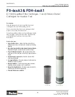
Velcon has qualified the FO-6xxA3 pleated
media filter cartridges to EI Specification 1590,
“Specifications and Qualification Procedures for
Aviation Fuel Microfilters.”
INSTALLATION OF VESSEL
1. Identify the Filter inlet and outlet by the markings
provided on the vessel piping. The Filter must be
installed in the correct direction of fl ow to perform
properly and to avoid damage to the system.
2. INLET and OUTLET PIPING should be carefully
aligned to avoid stressing the Filter connections
during installation. Installation of shut-off valves on
either side of the Filter is recommended so that it
can be independently drained for cartridge change
or inspection.
CAUTION
STEPS 3 AND 4 SHOULD BE
PERFORMED BEFORE REMOV-
ING HINGE OR PIVOT MOUNTED
COVER TO ENSURE STABILITY OF
THE FILTER.
3. Bolt the fi lter to a stable base.
4. Carefully install correct gaskets on the inlet and
outlet connections and connect to the inlet and
outlet piping.
5. Connect any accessories that are not already
installed. See Accessory Parts List and literature
as required.
6. Cartridges are normally packed separately.
Open the vessel cover and install cartridges as
explained on page 8 and as per enclosed element
stack drawing. Tighten nuts on tie rods until the
rubber washers begin to curl. Do not over-torque.
sequence.
7. Be sure the cover gasket is in place and properly
aligned. Replace cover and secure tightly.
NOTE
FILTERS MUST BE PROVIDED WITH
PRESSURE RELIEF VALVES IF THE
SYSTEM HAS POSITIVE DISPLACEMENT
PUMPS UPSTREAM OR AUTOMATIC
SHUT-OFF VALVES DOWNSTREAM OF
THE VESSEL.
START UP PROCEDURE
If the Velcon Filter has the accessories listed below, they
should be placed in the following positions:
1. Manual drain valves closed.
2. Manual air eliminator valve open.
3. The valves in the inlet and outlet piping should be
closed.
4. The pressure gauge valve to OFF position. For
Filters equipped with selector valves, this is done
by turning the handle outward so that the arrow
points toward the vessel.
For information on operation of accessories, turn to
Accessory Instructions in the back of the manual.
After the valves have been positioned as outlined, the unit
is ready to be filled.
The following operating instructions can be used for initial
start-up and for subsequent start-ups after installation of
replacement elements or servicing of the unit.
1. Start the system pump.
2. Slightly open the inlet valve, allowing the Filter to
slowly fi ll with fl uid. (Take about 10 – 15 minutes
to fi ll the vessel to eliminate the possibility of an
internal fi re.)
3. If the unit is equipped with a manual air eliminator
valve, leave the valve cracked open until the fl uid
fl ows from the opening; then close quickly.
4. If equipped with an automatic air eliminator, the
unit is fi lled when the air eliminator stops fl owing
air. When the Velcon Filter is fi lled with fl uid, slowly
open the valve on the inlet line, then slowly open


