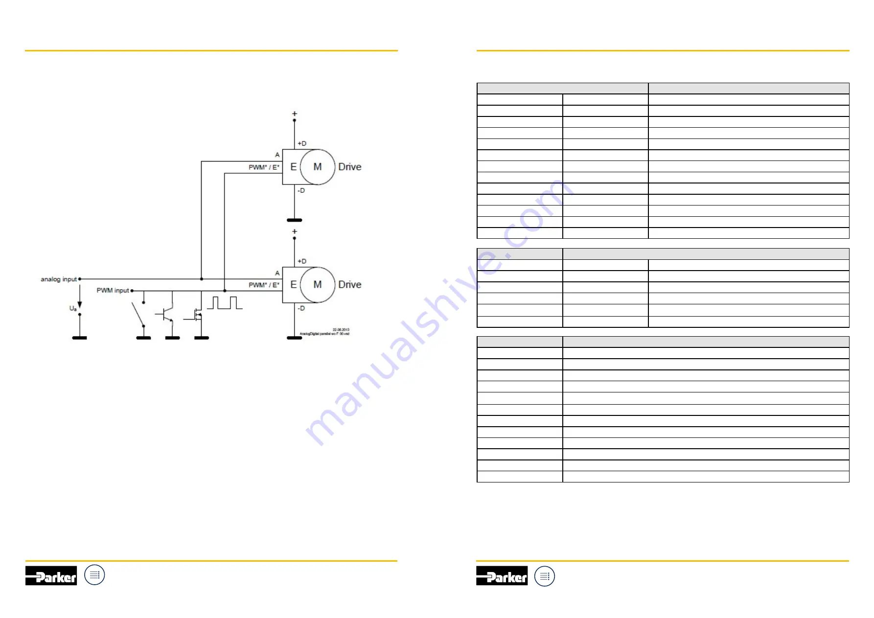
5.16 Interface Parallel Configuration
The Drives can be used in a parallel configuration in the PWM driven modes as well as in analog driven
modes and also in the combines analog / PWM mode in such a way that the control lines are connected in
parallel as shown in below for the example of two Drives.
There is no limitation from the Drive‘s point of view in paralleling them. Nevertheless from the CCU’s point of
view it has to be considered that all of the Drives needs a certain current each on the signal lines PWM* / E*
and A. This has to be taken into account for dimensioning the driver stage which controls digitally via the
PWM* / E* inputs of the Drives or which controls analog via the A inputs of the Drives. The output driver
stage of the CCU needs to be capable of driving minimum the input currents of PWM* / E* and / or A times
the number of the Drives.
5.17 Units and Acronyms
Unit
Physical Quantity
%
percent
Proportionality
Ω
Ohm
Electrical Resistance
°C
degree Celsius
Temperature
A
Ampere
Current
h
hours
Time
dBA
deciBel (A-weighting)
Sound Pressure Level
Hz
Hertz
Frequency
min
minute
Time
Pa
Pascal
Pressure
RPM
Revolutions per minute
Rotation Frequency
s
second
Time
V
Volt
Voltage
W
Watt
Power
Prefix
Dimension
M
10
6
mega
k
10
3
kilo
m
10
-3
milli
ų
10
-6
micro
n
10
-9
nano
p
10
-12
pico
Key Word
Description
AMPL_IN
Amplitude PWM Input Signal
CCU
Custom Control Unit
Drive
Motor with axially Integrated Electronics
IGN
Ignition (KL15)
PWM
Pulse Width Modulation
R
i
Input Resistance
SBL
Sealed Brushless
T
Temperature
T
AMB
Ambient Temperature
U
B
Supply Voltage
U
N
Nominal Supply Voltage
rms
Root Mean Square
20
21
Parker Hannifin
Cylinder and Accumulator
Division Europe
Parker Hannifin
Cylinder and Accumulator
Division Europe
Manual and Installation Guide
Manual and Installation Guide
QDC
for electrified mobile applications
QDC
for electrified mobile applications


