OEM750 •
➁
Installation
13
Quick Test: OEM750 with Separate Indexer
1. Complete steps 1 – 7 from the
Quick Test, but turn DIP SW3-#3 ON to disable
the automatic test function.
2. To connect a
Compumotor indexer to the OEM750’s 25 pin D-connector, use the
cable provided with the indexer. Plug the cable into the OEM750’s 25 pin D-
connector. No additional wiring is necessary. Refer to the indexer’s user guide for
specific instructions for operating the Compumotor indexer.
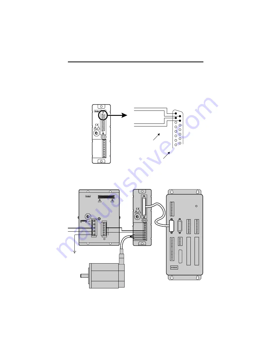
To connect a
non-Compumotor indexer, connect step and direction outputs from
the indexer to the OEM750's 25 pin D-connector, according to the next drawing.
1
2
14
15
Step+ Input
Step- Input
Di Input
Direction- Input
1
14
2
15
25 Pin
D-Connector
on OEM750
Inputs are +5VDC
maximum
7
5
0
D
RIV
E
7
5
0
D
RIVE
REMOTE
REF
CURRENT
DUMP
VDC+
VDC-
A+
A-
B+
B-
PWR/FLT
OEM
series
!
Test Configuration – OEM750 Step and Direction Inputs
The next drawing shows the test configuration with a separate indexer, a motor,
and an OEM300 Power Module.
Compumotor
OEM
series
M
O D U L E
PO
WER
AC
AC
EARTH
*INSTALL JUMPER FOR 90-132 VAC 50/60 Hz
REMOVE JUMPER FOR 180-265 VAC 50/60 Hz
POWER
GND
+75VDC @ 2.7A
GND
(RESERVED)
DANGER
HIGH
VOLTAGE
DANGER
HIGH
VOLTAGE
USE ONLY
INSULATED WIRE
FOR JUMPER*
Indexer
OEM Drive
Power Supply
Motor
AC
Power
REMOTE
REF
CURRENT
DUMP
VDC+
VDC-
A+
A-
B+
B-
PWR/FLT
OEM
series
!
7
5
0
D
RIV
E
7
5
0
D
RIVE
Test Configuration with OEM750 and Separate Indexer
Summary of Contents for OEM750
Page 64: ... Tuning Specifications OEM750 56 ...
Page 90: ...EMC INSTALLATION GUIDE OEM750 OEM750X 82 ...
Page 94: ...INDEX OEM750 86 ...


