32 - PVD3627-August 2011
3.1.10.
The motors fed by converters are subject to higher stresses than in case of
sinusoidal power supply. The combination of fast switching inverters with cables will
cause over voltage due to the transmission line effects. The peak voltage is
determined by the voltage supply, the length of the cables and the voltage rise time.
As an example, with a rise time of 200 ns and a 30 m (100 ft) cable, the voltage at
the motor terminals is twice the inverter voltage.
Voltage withstand characteristics of MGV series
The insulation system of the MGV motors is designed to withstand high repetitive
pulse voltages and largely exceeds the recommendations of the IEC/TS 60034-25 ed
2.0 2007-03-12 for motors without filters up to 480V AC.
Higher supply voltages are available on request.
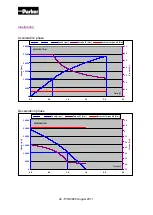
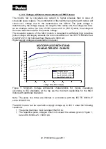
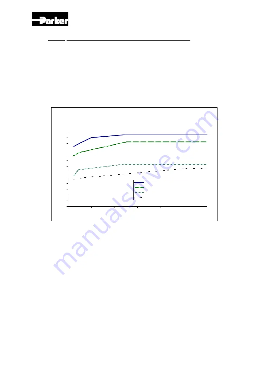
Figure 1: Minimum Voltage withstands characteristics for motors insulations
according to IEC standards. At the top are the minimum capabilities for the MGV
motors with additional insulation.
Note: The pulse rise times are defined in accordance with the IEC/TS 60034-17
ed4.0 2006-05-09.
The MGV motors can be used with a supply voltage up to 480 V under the following
conditions:
The pulse rise times must be longer than 50 ns.
The repetitive pulse voltages must not exceed the values given in figure 1,
Curve IEC 60034-25 : <500V AC.
MOTOR PULSE WITHSTAND
CHARACTERISTIC CURVES
0
0.2
0.4
0.6
0.8
1
1.2
1.4
1.6
1.8
2
2.2
2.4
2.6
0
0.2
0.4
0.6
0.8
1
1.2
Voltage Pulse Rise Time (µs)
P
eak V
o
lt
ag
e (
kV
)
Curve TM motors
Curve IEC 60034-25: <690V AC
Curve IEC 60034-25: <500V AC
Curve 60034-17: <500V AC
Curve MGV motors

