background image

➁ 

Getting Started

5

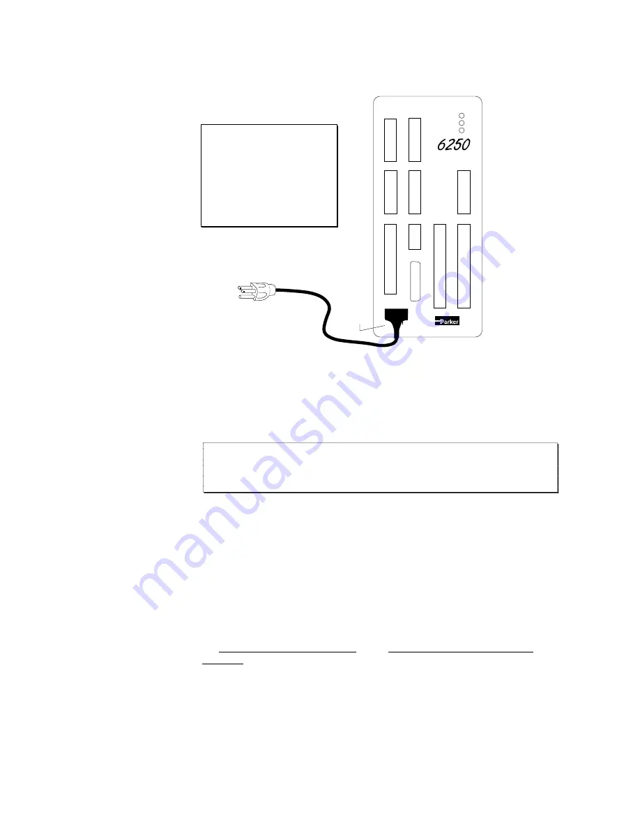
 Connect Power Cable

The 6250 is shipped with an 8-foot power cable that is prewired and keyed.  Attach the power
cable to the 6250's 

POWER

 connector as illustrated below.

WARNING

DO NOT APPLY POWER

TO THE 6250 UNTIL

INSTRUCTED TO DO SO

IN THE FOLLOWING
TEST PROCEDURE.

POWER

EARTH

N/A

NEUT

LINE

C o m p u m o t o r

2 - A X I S   S E R V O
C O N T R O L L E R

85 - 240VAC

If you have a power source other than
85-240VAC, refer to Chapter 8 for
specifications on alternative input power.

Protective

Rubber

Boot

  Test Procedure

Use the following procedure to test the 6250's power and RS-232C connections.  In Chapter 3,
Installation, you will test the analog output, end-of-travel and home limits, encoders, RP240,
joystick, and programmable I/O.

Apply power to the 6250 by plugging the power cable into a grounded power source.

CAUTION

The earth ground connection must be made by plugging into a grounded receptacle
or by physically connecting the green wire to earth ground.

Watch the LEDs on the 6250.  The STATUS LED should be green, indicating the 6250 is ready
for operation.  The other two LEDs should be red because the drives are not yet enabled with the

DRIVE11

 command.

If the STATUS LED is red, or if none of the LEDs illuminate, check your power source and cable
connections.  If these connections seem correct, disconnect power and consult Chapter 9,
Troubleshooting.

If you are using the 6000 DOS Support Disk, go to the 

Set-up

 menu and move the cursor down

to 

CHECK OUT

 and press 

ENTER

 to automatically verify the communication interface to the

6250.

If the interface is not successful (

Device not Ready

 message will flash on the screen), refer

to the RS-232C troubleshooting procedures in Chapter 9, Troubleshooting.

Initiate the terminal emulator in Motion Architect or in the 6000 DOS Support Disk (refer to
the  Motion Architect User Guide or the 6000 DOS Support Disk Quick
Reference
 if necessary).  You could also use your own terminal emulator package.

Press the RETURN key.  The cursor should move down one or two lines each time you press the
RETURN key.  If the cursor does not move as described, refer to the RS-232C troubleshooting
procedures in Chapter 9, Troubleshooting.

Summary of Contents for 6250

Page 1: ...Compumotor Division Parker Hannifin Corporation p n 88 013413 01B October 18 1993 6250 Servo Controller User Guide ...

Page 2: ...f any kind or nature whatsoever including but not limited to lost profits arising from or in any way connected with the use of this user guide or the equipment Compumotor Division of Parker Hannifin Corporation 1993 All Rights Reserved The information in this user guide including any apparatus methods techniques and concepts described herein are the proprietary property of Parker Compumotor or its...

Page 3: ...lute position register is reset to zero Pg 49 Inputs Debounce Time New Feature The INDEB command has been included to allow you to set the debounce time for the 24 general purpose programmable inputs and the 2 trigger inputs The range is 1 250 ms in even increments The default debounce time is 4 ms for the 24 inputs and 25 ms for the trigger inputs Pg 58 61 Power Input AC Correction The power conn...

Page 4: ...DREADI1 command allows continual input from the RP240 numeric keypad or the function keys when used in conjunction with DREAD and or DREADF Standard RP240 menus should not be used in this mode Data can be read into numeric variables only Do not assign the same variable to read numeric and function key data Power up default Mode clarification On power up the 6200 defaults to a mode in which it cont...

Page 5: ...tion 13 Programmable Inputs Outputs Connections 13 Trigger Input Connections 14 RP240 Front Panel Connections 15 Joystick and Analog Input Connections 15 ANI Analog Input Connections 6250 ANI Option Only 16 Extending 6250 System Cables 17 Installation Verification 17 What s Next 19 Chapter 4 Servo Tuning 2 1 Servo System Terminology 21 Servo Tuning Terminology 21 Position Variable Terminology 22 S...

Page 6: ...72 Variables Binary Numeric and String 73 RS 232C Daisy Chaining 76 Chapter 6 Advanced 6250 Features 7 9 S Curve Profiling 79 X Y Linear Interpolation 81 Chapter 7 6250 Programming Tips 8 3 Creating Programs Subroutines 83 Subroutines 84 Stored Programs and Non volatile Memory 84 Automatic Program Execution 85 Controlling Execution of Programs and the Command Buffer 85 Program Flow Control 87 Unco...

Page 7: ... in Chapter 4 Refer to the 6000 Series Software Reference Guide for detailed descriptions of the 6000 Series commands used in Chapters 4 through 7 Servo Tuning Instructs you on how to tune the 6250 for your application Sample applications are provided Complete all tuning instructions before implementing motion features Basic 6250 Features Describes the 6250 s basic user features and instructs you ...

Page 8: ...dures in Chapter 4 are based primarily on using the Servo Tuner option for Motion Architect After successfully completing all procedures in Chapter 4 you may proceed to Chapters 5 through 7 to implement the 6250 s user features in your application Conventions Clockwise CW Counter clockwise CCW Directions Clockwise CW Counter clockwise CCW Throughout this user guide and the 6000 Series Software Ref...

Page 9: ...inal User programs are stored in the 6250 s battery backed RAM The 6250 also provides operator interface capabilities when used with the Compumotor RP240 Front Panel The 6250 comes standard with support software for the Microsoft Windows and DOS operating environments Motion Architect is an innovative easy to use Microsoft Windows based programming aide to help you easily create and implement comp...

Page 10: ...nterrupt program execution on error conditions 2 axis linear interpolation standard Variable storage conditional branching and math capability Program debug tools single step and trace modes breakpoints and simulation of I O Internal power supply Direct interface to RP240 Front Panel Operates stand alone or interfaces to PCs PLCs 3 wire RS 232C interface to PC or dumb terminal 1 2 MHz pre quadratu...

Page 11: ...hitect diskettes Motion Architect Servo Tuner diskette optional Motion Architect User Guide DOS Support Disk DOS Support Disk Quick Reference 8 foot AC power cord 6250 or 6250 ANI if so ordered 88 013413 01 88 012966 01 95 013070 01 95 013070 02 95 013714 01 88 013056 01 95 012266 01 88 013258 01 71 009039 01 The 6250 ANI is an optional version of the 6250 which provides two 10V 14 bit analog inpu...

Page 12: ... the following communication parameters You can configure these parameters by using one of the terminal emulation software packages listed above in Computer to Terminal Conversion If you are using Motion Architect or the 6000 DOS Support Disk verify that the baud rate data bit parity and stop bit parameters are set as follows Baud Rate 9600 Data Bits 8 Parity None Stop Bits 1 Full Duplex XON XOFF ...

Page 13: ...on the 6250 The STATUS LED should be green indicating the 6250 is ready for operation The other two LEDs should be red because the drives are not yet enabled with the DRIVE11 command If the STATUS LED is red or if none of the LEDs illuminate check your power source and cable connections If these connections seem correct disconnect power and consult Chapter 9 Troubleshooting If you are using the 60...

Page 14: ...ing installation precautions WARNING Always remove power to the 6250 before performing wiring installation or changing DIP switch settings Heat Humidity Operate the 6250 system at an ambient temperature between 32 and 122 F 0 to 50 C Keep the relative humidity below 95 Electrical Noise For more information on electrical noise refer to Appendix A Minimize the potential for electrical noise before i...

Page 15: ...in an enclosure that will protect it from atmospheric contaminants such as oil metal moisture and dirt Refer to the National Electrical Manufacturers Association NEMA specifications that pertain to your particular operating environment The drawing below illustrates the 6250 s dimensions 4 20 106 68 2 70 68 58 0 75 19 05 10 80 274 32 10 00 254 00 Provision for 10 Mounting Screws 4 Plcs 0 80 20 32 1...

Page 16: ... this information you can connect the drives to the 6250 s 9 pin screw terminal connectors as illustrated below I O circuit drawings are provided in Chapter 8 Hardware Reference Pin Name In Out Description 1 SHLD Shield internally connect to chassis earth ground 2 COM Signal common for shutdown 3 SHTNC OUT Shutdown relay output to drives that require a closed contact to disable the drive The shutd...

Page 17: ... GND SHLD APEX Series Drive A pin 13 A pin 14 SRVON pin 23 Voc pin 24 B pin 29 B pin 30 Z pin 43 Z pin 44 VIN pin 49 AGND pin 50 6250 A A SHTNO 5V B B Z Z CMD CMD NOTE Apex Series A connected to 6250 s A Apex Series A connected to 6250 s A 1 8 15 6250 SHLD COM SHTNC SHTNO DFT AGND ANI CMD CMD DRIVE 1 BL Drive User I O Connector ENCODER 1 5V A A B B Z Z GND SHLD 9 NOTE These connections will work o...

Page 18: ... CMD CMD DFT SHTNO COM AGND 6250 PLB 1 UD2 UD5 Drives UR3 UR4 or UR8 Rack G1 G2 VEL2 VEL1 SCREEN 0V FAULT EXT DIS LSW1 LSW2 SHLD COM SHTNC SHTNO DFT AGND ANI CMD CMD DRIVE 1 18V AC 0V 18V AC 15V 0V 15V 0V RESET READY PSU FAULT PL9 1 UD2 UD5 Drives 15V LSW1 LSW2 VEL2 VEL1 0V FAULT EXT DIS 6250 SHTNO CMD CMD AGND DFT COM NOTE These connections will work only if UD2 5 jumper LK1 is set to the 0V posi...

Page 19: ...jumper LK3 is set to position A not the factory default position 6250 SHLD COM SHTNC SHTNO DFT AGND ANI CMD CMD ENCODER 1 DRIVE 1 Z Drive 5V A A B B Z Z GND SHLD 1 13 25 14 ENABLE ENABLE RTI RTI RTO RTO GND Tx Rx GND CHA CHA CHB CHB CHZ CHZ ANALOG ANALOG I O 1 INDEXER CONNECTOR To 6250 Logic Gnd To 6250 Programmable Output Pin 7 and 19 are FAULT RESET and FAULT RESET respectively These connections...

Page 20: ...ly if the motor is not coupled to the load Use the TLIM or TAS commands to check the status of the limit switches CAUTION RUNAWAY CAUTION If a runaway occurs motor starts moving usually at the fastest possible velocity due to servo instability the 6250 will shut down the drive if the maximum encoder position error set with the SMPER command is exceeded before an end of travel limit either hardware...

Page 21: ...8 IN A Channel Brown A channel quadrature signal from encoder 7 IN A Channel Brown White A channel quadrature signal from encoder 6 IN B Channel Green B channel quadrature signal from encoder 5 IN B Channel Green White B channel quadrature signal from encoder 4 IN Z Channel Orange Z channel quadrature signal from encoder 3 IN Z Channel Orange White Z channel quadrature signal from encoder 2 Ground...

Page 22: ...hange inputs from sourcing to sinking All 24 programmable inputs are pulled up to 5V by connecting the IN P terminal to the 5V terminal on the AUX connector If you wish to have the inputs sink current instead of source current you can connect IN P to GND For compatibility with equipment operating at 24VDC the inputs may be pulled up to 24VDC by using an external power supply The trigger inputs TRG...

Page 23: ...ors 2 Foot Cable provided with VM50 VM50 snaps on to any standard DIN Rail Trigger Input Connections The 6250 provides two trigger position latch inputs Like the programmable inputs described earlier trigger inputs can be connected to PLC outputs discrete switches or electronic sensors and are monitored under program control The status of triggers A and B is represented respectively by bits 25 and...

Page 24: ... should be adjusted so that its resistance is close to 0Ω when the joystick is all the way to one side and about 1KΩ when the joystick is all the way to the other side Also connect a 1KΩ resistor between the analog input and 5V Joystick Connector Pin Outs The JOYSTICK connector is a 25 pin D connector The pin out descriptions are provided in the table below The 6250 s internal analog input circuit...

Page 25: ...nge could be used to quickly move to a location while the low range could be used for accurate positioning Refer to the illustration above When this input is not connected the low velocity range is selected Joystick Release Input The joystick release input allows you to indicate to the 6250 that you have finished using the joystick and program execution may continue with the next statement When a ...

Page 26: ...tion below 22 AWG wire is the minimum recommended wire size Use twisted pair shielded cables and connect the shield to the SHLD terminal on the 6250 connector Leave the other end of the shield disconnected Do not route these signals in the same conduit or wiring trays as high voltage AC wiring Limit and trigger inputs are internally pulled up to 5VDC and are TTL compatible In electrically noisy en...

Page 27: ...1Ø SOFFSØ Ø SOFFS ØØ5 ØØ5 SOFFS ØØ5 ØØ5 TDAC response output voltage axis 1 axis 2 Encoder Feedback Enter the PSETØ Ø command to set the commanded motor position on both axes to zero Enter the TPE command to determine the actual motor position The response should be close to TPE Ø Ø both motors at or about position zero Enter the TPC command to determine the commanded motor position The response s...

Page 28: ...le the motor to the load and couple the encoder to the motor or load as appropriate Step Perform the Basic System Configuration NOTE The set up commands referred to in this step are not saved in the 6250 s battery backed RAM Therefore we suggest you add them to the startup STARTP program For information in defining the startup program refer to Automatic Program Execution on Power Up in Chapter 7 P...

Page 29: ... wide variety of application requirements but not all features are appropriate for every application Therefore you must first determine the necessary motion features you need for your application Once you have done that you can proceed to Chapter 4 to tune the 6250 and Chapters 5 through 7 to find out how to implement the 6250 s motion control features in your application Step Tune the Servo Syste...

Page 30: ...ning Terminology The 6250 uses a digital control algorithm to control and maintain the position and velocity The digital control algorithm consists of a set of numerical equations used to periodically once every servo sampling period calculate the value of the control signal output The numerical terms of the equations consist of the current commanded and actual position values plus a few from the ...

Page 31: ...ity acceleration change such that the control algorithm would calculate a control signal less than the limit This phenomenon of reaching the output limit is called controller output saturation When saturation occurs increasing the gains does not help improve performance since the motor is already operating at its maximum level Position Variable Terminology In a servo system there are two types of ...

Page 32: ...actors such as the desired profile the motor limitation the dynamic characteristics of the system etc For example if the value of the velocity V command is higher than the maximum velocity the motor can physically achieve then when the motor is commanded to travel at this velocity the actual position will always lag behind the commanded position and a position error will accumulate no matter how h...

Page 33: ...When we investigate the plot of the position response versus time there are a few measurements that you can make to quantitatively assess the performance of the servo Overshoot the measurement of the maximum magnitude that the actual position exceeds the position setpoint It is usually measured in terms of the percentage of the setpoint value Rise Time the time it takes the actual position to pass...

Page 34: ...e of the servo action The intermediate position setpoints calculated by the trajectory generator is updated at a slower rate then the servo position correction This command allows you to optimize this for your application The default setting SSF4 is sufficient for most applications STRGTD STRGTE STRGTT STRGTV Target Zone Distance Target Zone Mode Enable Target Zone Timeout Period Target Zone Veloc...

Page 35: ...ional SGP Improve Improve Improve Improve Improve Integral SGI Degrade Degrade Improve Improve Improve Velocity Feedback SGV Improve Improve Degrade Velocity Feedforward SGVF Improve Acceleration Feedforward SGAF Improve Proportional Feedback Control SGP Proportional feedback is the most important feedback for stabilizing a servo system When the 6250 uses proportional feedback the control signal i...

Page 36: ...acking error when the system is commanded to cruise at constant velocity Controlling Integral Windup If integral control SGI is used and an appreciable position error has persisted long enough during the transient period time taken to reach the setpoint the control signal generated by the integral action can end up too high and saturate to the maximum level of the controller s analog control signa...

Page 37: ...t constant velocity The tracking error is mainly attributed to three sources friction torque load and velocity feedback control SGV Velocity feedforward control is directed by the Servo Gain Velocity Feedforward SGVF setting which is in turn multiplied by the rate of change velocity of the commanded position to produce the control signal Consequently because the control signal is now proportional ...

Page 38: ...t use a manual emergency stop switch to shutdown the drive s power supply You can also use the EN B L input to disable the 6250 s analog output signal St ep 1 Make sure the power to the motor drive is off St ep 2 Apply power to the 6250 only and issue the DRIVE11 command Measure the 6250 s analog output between the CM D and CM D terminals on the DR I V E connector with both an oscilloscope to chec...

Page 39: ...ckwise direction The motor will stop when the maximum allowable position error is exceeded If the load has a large friction component you may need to use a larger offset SOFFS command to affect motion d Use the TPE command again to observe the encoder position value The value should have increased from the value observed in Step 7 b If the encoder reading decreases when using a positive SOFFS sett...

Page 40: ...in the iterative tuning process in Step 3 below g Click on the Sampling button in the Data Acquisition display In the dialog box select the data sampling period and frequency of samples for Motion Architect s data gathering function to be used in Step 3 below St ep 2 Tune the drive to output the desired velocity at a given voltage from the 6250 a If your system has mechanical stops manually move t...

Page 41: ...e drive to achieve a first order response no overshoot as illustrated below repeat Steps 3 a and 3 b as necessary Commanded Velocity Actual Velocity Velocity Time St ep 4 Proceed to the Controller Tuning Procedure section to tune the 6250 Motion Architect Automatic Gain Selection Feature The drive scale factor and step response information gathered in the latest Drive Tuner module session can be u...

Page 42: ...tion transducer potentiometer LVDT RVDT etc to pick up the load s or motor s position displacement and monitoring the transducer output on a digital storage oscilloscope St ep 2 Select the 6250 s sampling frequency ratios SSFR The 6250 s control signal is computed by the digital signal processor DSP The velocity of the commanded position the velocity of the encoder position and the integral of the...

Page 43: ... High natural frequency system Setting the Sampling Frequency Ratio Select a sampling ratio appropriate to your system now before you proceed to tune each gain In Motion Architect s Controller Tuner module select the System menu from the Setup pull down menu and select the appropriate servo sampling SSFR value If you are not using Motion Architect enter the appropriate SSFR command If you change t...

Page 44: ...ning Gains display show the new gain settings a In the Data Acquisition display select the Start button to trigger the step input move and gather data If you are not using Motion Architect enter GO1 or GO 1 depending on which axis is being tuned at the time b Observe the plot of the commanded position versus the actual position in the Graph Display area or on the oscilloscope If the response is al...

Page 45: ...36 6250 Servo Controller User Guide START OR Increase SGP UNTIL OR Decrease SGV UNTIL Increase SGV UNTIL OR OR Decrease SGV UNTIL STOP OR Decrease SGP UNTIL OR Decrease SGV UNTIL Increase SGV UNTIL ...

Page 46: ... digital oscilloscope If it saturates then lower the integral output limit by using the SGILIM command This should help reduce the overshoot and shorten the settling time Sometimes even if the analog output is not saturated you can still reduce the overshoot by lowering SGILIM to a value less than 10V However lowering it too much can impair the effectiveness of the integral feedback 3rd You can st...

Page 47: ...y The objective is to increase SGAF until the lag is reduced to a level suitable for your application Tuning Scenario The following tuning scenario presents an actual example of tuning Compumotor 6250 Servo Controller with a Digiplan UD Drive system with a brushed motor and unknown load inertia The UD Drive operates in velocity mode therefore the 6250 s analog control signal output is a velocity c...

Page 48: ...r the SGP was too high Next we should try raising the SGV gain to see if it could damp out the overshoot and chattering SGP 105 SGV 2 St ep 5 After the SGV gain was raised to 2 6 the overshoot was reduced but chattering was still quite pronounced This meant either one or both of the gains was too high The next step should be to lower the SGV gain first SGP 105 SGV 2 6 St ep 6 Lowering the SGV gain...

Page 49: ...11 When we raised the SGV gain to 2 52 the step response became fast and very stable SGP 70 SGV 2 52 Target Zone Move Completion Criteria Under default operation Target Zone Mode not enabled the 6250 s move completion criteria is simply derived from the move trajectory The 6250 considers the current preset move to be complete when the commanded trajectory has reached the desired target position af...

Page 50: ... a distance of 8 000 steps D8ØØØ must end up between position 7 995 and 8 005 and settle down to 0 5 rps within 500 ms 1 2 second after the commanded profile is complete Damping is critical To ensure that a move settles within the distance zone it must be damped to the point that it will not move out of the zone in an oscillatory manner This helps ensure the actual velocity falls within the target...

Page 51: ...50 ANI Option only RP240 Front Panel Interface Host Compumotor Control Variables RS 232C Daisy chaining Before You Proceed With This Chapter CAUTION To ensure proper installation and operator safety you should complete all the installation and test procedures provided in Chapter 2 and Chapter 3 and complete the tuning procedures in Chapter 4 before proceeding with any of the motion programming pro...

Page 52: ...rograms For more detailed user information refer to the 6000 DOS Support Disk Quick Reference Motion Architect Motion Architect is an intuitive Microsoft Windows based programming tool A brief description of Motion Architect s basic features is provided below For more detailed user information refer to the Motion Architect User Guide System Configurator and Code Generator Automatically generate co...

Page 53: ...curs the 6250 stops motion at the rate set with the LHAD command and terminates program execution No drive shutdown will result unless it is initiated with an ERRORP error program Chapter 3 Motor Driver Connections End of travel Limit Inputs End of travel limits prevent the load from crashing through mechanical stops an incident that can damage equipment and injure personnel You can use hardware o...

Page 54: ...lues in encoder steps sec for the motion trajectory calculations All distance D and PSET values are entered in encoder steps these values are internally represented as encoder steps Acceleration Deceleration Scaling SCLA PSCLA If scaling is enabled SCALE1 all accel decel values entered are internally multiplied by the acceleration scaling factor SCLA to convert user units sec2 to encoder steps sec...

Page 55: ... 100 999 0 01 0 00 9 999 999 99 2 1000 9999 0 001 0 000 999 999 999 3 10000 99999 0 0001 0 0000 99 999 9999 4 100000 999999 0 00001 0 00000 9999 99999 5 NOTE FRACTIONAL STEP TRUNCATION NOTE If you are operating in the incremental mode MAØ when the distance scaling factor SCLD and the distance value are multiplied a fraction of one step may possibly be left over This fraction is truncated when the ...

Page 56: ...be large enough to accommodate the moves or a new zero point must be defined using the PSET command before each move NOTE To ensure proper motion when using soft end of travel limits be sure to set the LSCW value to a greater absolute value than the LSCCW value Example In this example the hardware limits are enabled on axes 1 and 2 Deceleration rates are specified for both software and hardware li...

Page 57: ...gure C The final approach direction HOMDF is CW and the home edge HOMEDG is the CW edge NOTE To better illustrate the direction changes in the backup to home operation the illustrations in the remainder of this section show the backup to home movements with varied velocities In reality the backup to home movements are performed at the same velocity defined with the HOMVF command A CW home move is ...

Page 58: ...ome Home Active Region CW Edge of Home Velocity CCW Limit Initial Position CW Limit Position Figure G Homing in a CCW Direction HOM1 with HOMBAC1 HOMEDG1 HOMDF1 CCW Edge of Home Home Active Region CW Edge of Home Velocity CCW Limit Initial Position CW Limit Position Figure H Homing in a CCW Direction HOM1 with HOMBAC1 HOMEDGØ HOMDF1 CCW Edge of Home Home Active Region CW Edge of Home Velocity CCW ...

Page 59: ...e continuous mode You should select the mode that will be most convenient for your application For example a repetitive cut to length application requires incremental positioning X Y positioning on the other hand is better served in the absolute mode Continuous mode is useful for applications that require constant movement of the load based on internal conditions or inputs not distance Refer also ...

Page 60: ...the absolute zero position You can set the absolute position to any value with the Set Position PSET command When the Go Home HOM command is issued the absolute position is automatically set to zero after the motor reaches the home position The direction of an absolute preset move depends upon the motor position at the beginning of the move and the position you command it to move to For example if...

Page 61: ... 5 seconds at which point it decelerates to a stop While in continuous mode motion can also be stopped if You issue an immediate Stop S or Kill K command The load trips an end of travel limit switch The load trips an input configured as a kill or stop input with the INFNCi C or INFNCi D commands respectively On The Fly Changes You can change velocity and acceleration on the fly while motion is in ...

Page 62: ...tand alone operation After defining and storing 6250 programs with a RS 232C terminal you can operate the 6250 as a stand alone controller A program stored in the 6250 may interactively prompt the user for input as part of the program via programmable I O thumbwheels an RP240 or an RS 232C terminal PLC interface The 6250 s programmable I O may be connected to most PLCs The PLC typically executes p...

Page 63: ...rovided later in the section labeled Host Computer Operation Programmable Inputs and Outputs Refer to Chapter 3 for I O connection instructions I O circuit drawings and specifications are provided in Chapter 5 There are 26 programmable inputs includes 2 trigger inputs on the AUX connector and 26 programmable outputs includes 2 auxiliary outputs on the AUX connector All the 6250 s inputs and output...

Page 64: ...it represents output 1 and the right most bit represents output 26 Command Description OUTFNC Query status of all outputs response indicating default conditions is OUTFNC1 A NO FUNCTION OUTPUT STATUS OFF OUTFNC2 A NO FUNCTION OUTPUT STATUS OFF response continues until all 26 outputs are reported OUTFNC1 Query status of output 1 response indicating default conditions is OUTFNC1 A NO FUNCTION OUTPUT...

Page 65: ...hen a hard or soft limit has been encountered If a hard or soft limit is encountered you will not be able to move the motor in that same direction until you clear the limit by changing direction D and issuing a GO command An alternative is to disable the limits with the LHØ command but this is recommended only if the motor is not coupled to the load Fault Output OUTFNCi F When assigned the Fault O...

Page 66: ...the absolute position counter to activate the output on position will not turn on the output until the next motion occurs Example Command Description OUTFEN1 Enable programmable output functions OUTFNC25 H Set OUT A output 25 as output on position output for axis 1 OUTFNC26 H Set OUT B output 26 as output on position output for axis 2 OUTPA1 Ø 5ØØØØ 5Ø Turn on OUT A for 50 ms when the actual posit...

Page 67: ... is 4 ms for the 24 general purpose inputs and 24 ms for the 2 trigger inputs TRG A TRG B If the first i is in the range 1 24 the specified debounce time is assigned to all 24 general purpose inputs If the first i is 25 or 26 the specified debounce is assigned only to the specified trigger input For example the INDEB5 6 command assigns a debounce time of 6 ms to all 24 general purpose inputs The I...

Page 68: ...e inputs again If a program is selected that has not been defined no program will be executed The INSELP command also determines how long the program select input must be maintained before the 6250 executes the program This delay is referred to as debounce time but is not affected by the INDEB setting The following examples demonstrate how to select programs via inputs Example Command Definition R...

Page 69: ...In both cases when the input is activated the current command being processed will be allowed to finish executing before the program is paused COMEXRØ Upon receiving a pause input only program execution will be paused any motion in progress will continue to its predetermined destination Releasing the pause input or issuing a C command will resume program execution COMEXR1 Upon receiving a pause in...

Page 70: ...C command You must define the jogging velocity with the Jog Velocity High JOGVH and Jog Velocity Low JOGVL commands The acceleration and deceleration of the JOG move can be configured using JOGA and JOGAD respectively If you are using S curve profiles you must also specify JOGAA and JOGADA You can define three different inputs for jogging CW Jog input INFNCi aJ CCW Jog Input INFNCi aK and Jog Spee...

Page 71: ...gram progc TSTAT Transfer statistics END End program INFNC1 1P Input 1 will select proga INFNC2 2P Input 2 will select progb INFNC3 3P Input 3 will select progc INFEN1 Enable input functions INSELP2 5Ø Enable scanning of inputs You can now execute programs by making a contact closure from an input to ground to activate the input Activate input 1 to execute program 1 proga Activate input 2 to execu...

Page 72: ...otor s TM8 Module follow the procedures below Step Wire your TM8 module to the 6250 as shown below Optional Sign Bit Programmable Input 1 Programmable Input 2 Programmable Input 3 Programmable Input 4 Programmable Input 5 6250 Servo Controller Pin 49 5VDC Pin 48 GND Programmable Output 1 Programmable Output 2 Programmable Output 3 1 2 3 4 5 6 7 8 5 GND I5 I4 I3 I2 I1 O5 O4 O3 O2 O1 TM8 Thumbwheel ...

Page 73: ...operation with thumbwheels The data valid input will be an input which the operator holds active to let the 6250 read the thumbwheels This input is not necessary however it is often used when interfacing with PLCs Command Description OUTPLC1 1 4 Ø 12 Configure PLC output set 1 as follows outputs 1 4 are strobe outputs no output enable bit 12 ms strobe time per digit read INPLC1 1 8 9 Configure PLC...

Page 74: ...ry depending on the value of Rplc and Vplc Out 5 24 Volts GND 74HCTxx 6 8 KΩ 47 KΩ Input Connection Ground Connection R Vplc Rplc Output Ground 5VDC On the A UX c onnec tor y ou can s ink cur rent on the input s by c onnect ing IN P t o GND ins tead of to 5V GND IN P 5V GND Pulled up to 5VDC sourcing Joystick Interface The 6250 has three 8 bit analog input channels CH1 CH3 The analog inputs are co...

Page 75: ... motion will occur allows for minor drift or variation in the joystick center position without causing motion Because the center voltage can be set to a value other than the exact center of the potentiometer s voltage range and because there could be two different velocity resolutions the CW velocity resolution may be different than CCW velocity resolution Because of finite voltage increments the ...

Page 76: ...rps high range or 1 rps low range End Deadband JOYEDB 2 2 Velocity 5 rps high range or 1 rps low range Binary 11111111 21 counts Binary 11101000 Binary 01110000 Binary 01011100 Binary 00010100 Binary 00000000 122 counts 20 counts 72 counts 21 counts Velocity Increases Velocity Increases CW Velocity CCW Velocity Analog Voltage Override Before you actually wire the analog inputs you can simulate the...

Page 77: ...mer by customer basis by customizing the 6250 s firmware Below are some examples of customizations to the ANI analog input Customization Examples With customization the ANI analog input can provide Position feedback information to the control loop A position command to the control loop A velocity command Velocity feedback A scaler to the velocity command A force or torque feedback signal A scaler ...

Page 78: ...n Key DREADI RP240 Data Read Immediate Mode DVAR Display Variable On RP240 DWRITE Display Text On The RP240 Display The example below demonstrates the majority of the 6000 Series commands for the RP240 Example Command Description DEF panel1 Define program panel1 REPEAT Start of repeat loop DCLEARØ Clear display DWRITE SELECT A FUNCTION KEY Display text SELECT A FUNCTION KEY DPCUR2 2 Move cursor to...

Page 79: ...s indicate the menu path when you press the corresponding function key below the menu item Program Label to RUN is MAIN FIND ALPHA TRACE STEP AXIS 1 L R AXIS 2 U D LO 0 5000 HI 10 0000 EDIT JOG 6250 REV 92 013471 01 1 0 6250 DSP REV 92 013472 01 1 0 DSP RP240 Confirm RESET YES NO IN 0000_0000_0000_0000_0000_0000_00 OUT 0000_0000_0000_0000_0000_0000_00 AXIS 1 CW 1 CCW 1 HOME 0 AXIS 2 CW 1 CCW 1 HOM...

Page 80: ...rrow keys Pressing an arrow key will start motion and releasing the arrow key will stop motion using the jog acceleration and deceleration values specified by JOGA and JOGAD The left and right arrow keys correspond to axis 1 CCW and CW motion The up and down arrows keys are for axis 2 You may select either the jog low velocity or the jog high velocity by pressing the appropriate LO HI function key...

Page 81: ... example is provided below 10 6000 Series Serial Communication BASIC Routine 12 6000 BAS 14 16 18 20 This program will set the communications parameters for the 22 serial port on a PC to communicate with a 6000 series 24 stand alone product 26 28 30 100 open com port 1 at 9600 baud no parity 8 data bits 1 stop bit 110 activate Request to Send RS suppress Clear to Send CS suppress 120 DATA set read...

Page 82: ...c Variables Using the Variable Type Conversion VCVT operator you can convert numeric values to binary values and vice versa The operation is a signed operation as the binary value is interpreted as a two s complement number Any don t cares x in a binary value is interpreted as a zero Ø If the mathematical statement s result is a numeric value then VCVT converts binary values to numeric values If t...

Page 83: ...Ø 5 VAR1 SIN 45 VAR1 VAR1 Ø 7Ø711 VAR1 SIN 6Ø VAR1 VAR1 Ø 866Ø3 VAR1 SIN 9Ø VAR1 VAR1 1 Ø RADIAN1 VAR1 SIN Ø VAR1 VAR1 Ø Ø VAR1 SIN PI 6 VAR1 VAR1 Ø 5 VAR1 SIN PI 4 VAR1 VAR1 Ø 7Ø711 VAR1 SIN PI 3 VAR1 VAR1 Ø 866Ø3 VAR1 SIN PI 2 VAR1 VAR1 1 Ø Cosine Example Response RADIANØ VAR1 COS Ø VAR1 VAR1 1 Ø VAR1 COS 3Ø VAR1 VAR1 Ø 866Ø3 VAR1 COS 45 VAR1 VAR1 Ø 7Ø711 VAR1 COS 6Ø VAR1 VAR1 Ø 5 VAR1 COS 9Ø VA...

Page 84: ... Response VARB1 XXØ1_XXØX_XXXX_XXXX_XXXX_XXXX_XXXX_XXXX Example VARB1 hØØ32 FDA1 h1234 43E9 VARB1 Response VARB1 ØØØØ_ØØØØ_11ØØ_ØØØØ_ØØ1Ø_1ØØØ_Ø1Ø1_1ØØØ Bitwise Or Example VARB1 h32FD VARB1 Response VARB1 11ØØ_Ø1ØØ_1111_1Ø11_ØØØØ_ØØØØ_ØØØØ_ØØØØ Example VARB1 VARB1 bXXX1 11Ø1 VARB1 Response VARB1 11X1_11Ø1_1111_1X11_XXXX_XXXX_XXXX_XXXX Example VARB1 hØØ32 FDA1 h1234 43E9 VARB1 Response VARB1 1ØØØ_Ø...

Page 85: ...ger i represents the number of the data program 1 9 You can create up to 9 separate data programs The data program is automatically given a specific program name DATPi The second integer represents the total number of data elements up to 6 500 you want in the data program Upon issuing the DATSIZ command the data program is created with all the data elements initialized with a value of zero The dat...

Page 86: ...TPTR command As indicated by the number of integers in the syntax the maximum number of variable values that can be stored in the data program per DATTCH command is 4 Each successive value from the DATTCH command is stored to the data program according to the pattern established by the third integer of the DATPTR command As an example suppose data program 1 is configured to hold 13 data elements D...

Page 87: ...the DATSIZ command The integer i represents the number of the data program Data programs can be deleted just like any other user program e g DEL DATP1 DATi From the data program specified with i assigns the numeric value of the data element currently pointed to by the data pointer to a specified variable parameter in a 6000 series command e g D DAT3 DAT3 Teach Mode Application Example In this exam...

Page 88: ...he data pointer to the first data element After each DATTCH value is stored to DATP1 increment the data pointer by 1 data element REPEAT Set up a repeat until loop JOY11 Enable joystick mode on both axes At this point you can start moving the axes into position with the joystick While using the joystick command processing is stopped here until you activate the joystick release input Activating the...

Page 89: ...ement 1 all data elements have been read HOM11 Move both axes back to the home position END End definition of the subroutine called DOPATH Step 5 Define the MAIN Program Include SETUP TEACH and DOPATH DEF MAIN Begin definition of the program called MAIN SETUP Execute the subroutine called SETUP TEACH Execute the subroutine called TEACH DOPATH Execute the subroutine called DOPATH END End definition...

Page 90: ...nd disable communications on a particular 6250 unit in the chain you must establish a unique device address using the unit s address DIP switches or the Daisy chain Address ADDR command DIP switches Instructions for accessing and changing these DIP switch settings are provided in the Optional DIP Switch Settings section in Chapter 8 Device addresses set with the DIP switches range from 0 to 7 ADDR...

Page 91: ...dress and an underline Command Description 1_A Request acceleration information from unit 1 A5Ø 5Ø Response from unit 1 Use the E command to enable disable RS 232C communications for an individual unit If all 6250 units on the daisy chain are enabled commands without a device address identifier will be executed by all units Because of the daisy chain s serial nature the commands will be executed a...

Page 92: ...ain requires stored programs in the master 6250 which can control program and command execution on the slave 6250s The example below demonstrates the use of the WRITE command to send commands to other units on the daisy chain NOTE The last unit on the daisy chain must have RS 232C echo disabled ECHOØ command Master 6250 s main program Command Description DEF main Program main L Indefinite loop WHI...

Page 93: ...ed reads data from the RP240 into variables 1 data1 2 data2 then sends the messages 3_Ddata1 data2 CR and 3_GO CR Command Description L Indefinite loop VAR1 DREAD Read RP240 data into variable 1 VAR2 DREAD Read RP240 data into variable 2 EOTØ Ø Ø Ø Turn off CR WRITE 3_D Send message 3_D down the daisy chain WRVAR1 Send variable 1 data down the daisy chain WRITE Send message down the daisy chain EO...

Page 94: ...tion and deceleration portions of the move profile see drawing below Decel Accel Time Decel Velocity Time Trapezoidal Accel Time Velocity Time S Curve Maximum Jerk Less Jerk S curves improve position tracking Because S curve profiling reduces jerk it improves position tracking performance in servo systems especially in linear interpolation applications S curve programming requirements To program a...

Page 95: ...ve profile in which there is no period of constant accel decel and jerk is at an absolute minimum see drawing below T T S Curve Aavg 1 2 Amax V A A max A avg AD max AD avg T T Pure S Curve Aavg 1 2 Amax V A A max A avg AD max AD avg AD AD Once you enter an Aavg value that is zero and satisfies 1 2 Amax Aavg Amax S curve profiling is enabled but only in the operation that uses that particular Aavg ...

Page 96: ...o 5 rps on both axes GO Execute motion on both axes T Axis 2 V 0 1 2 3 T Axis 1 V 0 1 2 3 Axis 1 executes a pure S curve profile that takes 1 second to reach a velocity of 5 rps and 1 second to return to zero velocity Axis 2 executes a trapezoidal profile that takes 0 5 seconds to reach a velocity of 5 rps and 0 5 seconds to return to zero velocity X Y Linear Interpolation The 6250 allows you to p...

Page 97: ...to 25 units sec2 PAD2Ø Set the path deceleration to 20 units sec2 PV2 Set the path velocity to 2 units sec D1Ø 5 Set the distance to 10 5 units on axes 1 2 respectively GOL11 Initiate linear interpolated motion on both axes see figure below a GOL command could have been issued instead of a GOL11 command Y Axis 2 X Axis 1 6 5 4 3 2 1 1 2 3 4 5 6 7 8 9 10 11 12 13 D1Ø 5 DØ Ø Velocity Time PV PA Line...

Page 98: ...s with the MEMORY command default is 21 400 bytes You can use the TMEM command to determine how many bytes are available in the program buffer and the TDIR command to determine what programs have been defined The programs defined may have variable lengths so you may have one long program or several short ones as long as the total length does not exceed the allocated memory capacity The commands th...

Page 99: ...non volatile memory Additional information that is stored in non volatile memory includes All variables numeric VAR binary VARB and string VARS Compiled contouring paths PCOMP Device Address ADDR Memory allocation MEMORY Power up program STARTP RP240 password DPASS RS 232C baud rate Servo gain sets SGSET A checksum is calculated over this user memory area each time on power up or reset A bad check...

Page 100: ...rogram access input is not activated you will receive the error message ACCESS DENIED For example once you issue the INFNC22 Q command input 22 is assigned the program access function and access to the DEF DEL ERASE MEMORY and INFNC commands will be denied until you activate input 22 Automatic Program Execution A program can be run automatically after the 6250 is powered up or reset Any program ma...

Page 101: ...parameters with subsequent GO commands while the axis is still in motion Refer to the Continuous Mode section in Chapter 5 for examples COMEXL The COMEXL command enables saving the command buffer and maintaining program execution when a hardware or software limit is encountered COMEXR The COMEXR command affects whether a pause input i e a general purpose input configured as a pause continue input ...

Page 102: ...nds are executed in the order in which they are received However certain commands can redirect the order in which commands will be processed The GOTO command is a branch without a return to a group of commands The GOSUB command is a compact way to execute a group of commands starting with a DEF command and ending with a END command then proceeding with the command following the GOSUB GOTO and GOSU...

Page 103: ...EPEAT or WHILE statement area unless an LN NIF UNTIL or NWHILE command has already been encountered If you wish to avoid this nesting situation use the JUMP command instead of the GOTO command Example Command Description DEF cut1 Begin definition of program cut1 HOM11 Send axes 1 and 2 to the home position WAIT 1AS bØXXX1 AND 2AS bØXXX1 Wait for axes 1 and 2 to come to a halt at home GOSUB prompt ...

Page 104: ...if variable 1 is less than variable 2 and variable 4 is greater than axis 1 actual position A binary variable VARB can be used within an expression if the variable is compared against another binary variable or a value When comparing a variable against another value or variable the relational operators and logical operators AND OR NOT are used Expression Description VARB1 VARB2 True expression if ...

Page 105: ...l 3FFD Timer Values The current timer value TIM can be used within an expression if the operand is compared against a numeric variable or value When making the comparison the relational operators and logical operators AND OR NOT are used Expression Description VAR1 TIM True expression if the value of variable 1 is less than the timer value Data Read from the Serial Port The READ command can be use...

Page 106: ...ping structures REPEAT UNTIL and WHILE REPEAT UNTIL All commands between REPEAT and UNTIL are repeated until the expression contained within the parenthesis of the UNTIL command is true The example below illustrates how a typical REPEAT UNTIL conditional loop works Command Description VAR5 Ø Initializes variable 5 to 0 DEF prog1Ø Defines program prog10 INFNC1 A Input 1 is not assigned a function u...

Page 107: ...d if the expression contained within the parentheses of the IF command is true If the expression is false the commands between ELSE and NIF are executed If the ELSE is not needed it may be omitted The commands between IF and NIF are executed if the expression is true Examples of these commands are provided below Command Description DEF prog1Ø Defines program prog1Ø INFNC1 A Input 1 is not assigned...

Page 108: ...og input channels using the ANVO command You can set the desired state of the 6250 s inputs and outputs via software commands You can enable the 6250 to display error messages when it detects certain programming errors as you enter them or as the program is run When the 6250 detects an error with a command you can issue the TCMDER command to find out which command has the error Trace Mode You can ...

Page 109: ... COUNT 3 PROGRAM PROG1 COMMAND LN LOOP COUNT 3 PROGRAM PROG1 COMMAND END The format for the Trace mode display is Program Name Command or Program Name Command Loop Count or Program Name Command Repeat Count or Program Name Command While Count Step To exit the Trace mode enter the following command Command Description TRACEØ Disables the Trace mode Single Step Mode The Single Step mode allows you t...

Page 110: ...puts that integrate the 6250 with other components in your system you can simulate the activation of these inputs and outputs so that you can run your programs without activating the rest of your system Thus you can debug your program independent of the rest of your system The 6250 uses two commands that allow you to simulate the input and output states desired The INEN command controls the inputs...

Page 111: ...e will be OUTFNC1 A PROGRAMMABLE OUTPUT STATUS DISABLED ON OUTFNC2 A PROGRAMMABLE OUTPUT STATUS DISABLED ON OUTFNC3 A PROGRAMMABLE OUTPUT STATUS DISABLED ON OUTFNC26 A PROGRAMMABLE OUTPUT STATUS OFF Notice that output 2 and output 4 have not changed state The output OUT command has no effect on disabled outputs Step To re enable the outputs use the OUTEN command Command Description OUTENEEEE Re en...

Page 112: ...nly the error prompt Identifying Bad Commands To facilitate program debugging the Transfer Command Error TCMDER command allows you to transfer the command that the controller detects as an error This is especially useful if you receive an error message when running or downloading a program because it catches and remembers the command that caused the error When the bad command is detected the contr...

Page 113: ...typically include actions such as shutting down the drive s activating or de activating outputs etc An error program template is provided on the DOS support software diskette that ships with the 6270 see file name ____ in the sub directory SAMPLES You can also refer to the error program set up example below Using the ERRORP command you can assign any previously defined program as the error program...

Page 114: ...nd Gosub Issue a DRIVE1 command to the axis that exceeded the allowable position error Verify that feedback device is working properly Reserved Bits Bits 1 8 10 13 32 are reserved Branching Types If the error condition calls for a GOSUB then after the ERRORP program is executed program control returns to the point at which the error occurred If you do not want to return to the point at which the e...

Page 115: ...1 command Step 4 Test the error handling Command Description L Loop command WRITE IN LOOP 1Ø 13 Send Message IN LOOP T2 Wait 2 seconds LN End the loop Message IN LOOP will be displayed once every 2 seconds INEN1 Disable input 1 and force it on for testing purposes This simulates the physical activation of input 1 Since the error program is called continuously until the branch to the error program ...

Page 116: ... of daisy chained 6250s Address settings Communication Parameters 3 wire Rx Tx and GND connection to the AUX connector Up to 8 units DIP switch Selectable see Optional DIP Switch Settings or use ADDR 9600 baud auto baud option see Optional DIP Switch Settings 8 data bits 1 stop bit no parity bit full duplex Inputs see also I O Pin Outs Circuit Drawings Home CW CCW Limits Joystick Trigger Joystick ...

Page 117: ...rive when no power is applied to the 6250 When the 6250 is powered up the shutdown relay remains active until you issue the DRIVE11 command Shutdown active DRIVEØØ This output is internally connected to COM Shutdown inactive DRIVE11 This output is disconnected from COM 4 OUT SHTNO Shutdown relay output to drives that require an open contact to disable the drive see circuit drawing below The shutdo...

Page 118: ...ector Input Connector 49 5VDC 5VDC 47 Output 1 LSB Input 1 LSB 45 Output 2 Input 2 43 Output 3 Input 3 41 Output 4 Input 4 39 Output 5 Input 5 37 Output 6 Input 6 35 Output 7 Input 7 33 Output 8 Input 8 31 Output 9 Input 9 29 Output 10 Input 10 27 Output 11 Input 11 25 Output 12 Input 12 23 Output 13 Input 13 21 Output 14 Input 14 19 Output 15 Input 15 17 Output 16 Input 16 15 Output 17 Input 17 1...

Page 119: ...s set to ØV and the shutdown outputs are activated this occurs independent of the DSP and the microprocessor Internal input circuit is identical to the limit circuit below Limits LIM1 2 Connector The following table contains the pin outs for the 6250 s limit LIM 1 2 9 pin screw terminal The internal limit input circuit is illustrated below Pin In Out Name Description Schematic 9 8 7 6 5 4 3 2 1 IN...

Page 120: ...only for daisy chaining multiple 6250s with one RS 232C circuit and to use the 6250 s auto baud rate feature NOTE The default settings address 0 baud rate 9600 are adequate for most applications Accessing the DIP Switch Package Use the following procedure to access the DIP switch package inside the 6250 CAUTION While handling the 6250 printed circuit assembly PCA be sure to observe proper groundin...

Page 121: ...ter the baud rate has been determined Switch 3 Switch 2 Switch 1 Device Address Change Switch 4 to the ON position Connect the terminal to the 6250 s RS 232C serial port on the AUX connector Power up the terminal Cycle power to the 6250 and immediately press the space bar several times The 6250 should send a message to the terminal confirming the baud rate i e 9600 You should now be communicat ing...

Page 122: ...d Can you repeat or re create the problem Do not attempt to make quick rationalizations about problems Random events may appear to be related but they are not necessarily contributing factors to your problem You must carefully investigate and decipher the events that occur before the subsequent system problem You may be experiencing more than one problem You must isolate and solve one problem at a...

Page 123: ...oper wiring 1 Ground Joystick Release input 2 Check wiring for opens shorts and mis wired connections Motor Runaway if encoder counts positive when turned clockwise 1 Direction connections reversed 1 Switch CMD with the CMD connection to drive No Motion 1 Status LED off or red 2 Limits engaged 3 Drive fault level incorrect 4 Improper wiring 5 Load is jammed 6 No torque from motor 7 Maximum positio...

Page 124: ...ng 1 Check and set resolution on 6250 with ERESx x RS 232C Troubleshooting If you are having problems communicating with the 6250 try the following procedure to troubleshoot the communications interface Power up your computer or terminal and then power up the 6250 The serial port of your computer terminal may require hardware handshaking If so you must disable handshaking with your terminal emulat...

Page 125: ...d how With what equipment is the unit interfaced What was the application What was the system environment temperature enclosure spacing unit orientation contaminants etc What upgrades if any are required hardware software user guide In the USA call Parker Compumotor for a Return Material Authorization RMA number Returned products cannot be accepted without an RMA number The phone number for Parker...

Page 126: ...noisy device such as a relay or solenoid is attached to the DC ground it may cause disturbances within the 6250 To solve a noise problem caused by DC mechanical relays and solenoids you can connect a diode backwards across the coil to clamp the induced voltage kick that the coil will produce The diode should be rated at 4 times the coil voltage and 10 times the coil current Using solid state relay...

Page 127: ... system is in the design process the designer should consider the following set of guidelines for system wiring in order of importance Put surge suppression components on all electrical coils Resistor capacitor filters MOVs Zener and clamping diodes Shield all remote connections use twisted pairs Shields should be tied to Earth at one end Put all microelectronic components in an enclosure Keep noi...

Page 128: ...ignment DAC Value of DAC Digital to Analog Converter Output DACLIM DAC Limit DAT Data Assignment DATA Data Statement DATPRG Define Data Set DATRST Reset Data Pointer DCLEAR Clear RP240 Display DEF Define a Program Subroutine DEL Delete a Program Subroutine DJOG Enable RP240 Jog Mode DLED Turn RP240 LEDs On Off DPASS Set RP240 Password DPCUR Position Cursor on RP240 Display DREAD Read Numeric Keypa...

Page 129: ...nd WHILE Statement Command Command Name Description ONCOND On Condition Enable ONIN On an Input Condition Gosub ONP On Program ONUS On a User Status Condition Gosub ONVARA On Variable 1 Condition Gosub ONVARB On Variable 2 Condition Gosub OR Or OUT Output State OUT Output Status OUTALL Multiple Output State OUTEN Output Enable OUTFEN Output Function Enable OUTFNC Output Function OUTLVL Output Acti...

Page 130: ...ransfer Output State TPC Transfer Position Commanded TPCA Transfer Position of Captured ANI Inputs TPCC Transfer Captured Commanded Position TPCE Transfer Position of Captured Encoder TPE Transfer Position of Encoder TPER Transfer Position Error TPROG Transfer Program TRACE Program Trace Mode Enable TRANS Translation Mode Enable TREV Transfer Revision Level TSGSET Transfer Servo Gain Set TSS Trans...

Page 131: ......

Page 132: ...controller 19 DIP switch settings auto baud address 77 105 drive fault level 19 inputs 58 jogging 62 outputs 55 system iv thumbwheel 64 connections AC power cable 5 analog input 15 ANI inputs 16 drive 9 encoder 12 factory default 3 installation process overview iv joystick 15 limits end of travel 11 home 11 PLC 65 RP240 15 RS 232C 4 daisy chain 76 thumbwheels 63 TM8 Thumbwheel Module 63 VM50 adapt...

Page 133: ...d as basis to activate output 56 linear interpolation 81 acceleration scaling PSCLA 46 end point 81 initiate motion GOL 81 velocity scaling PSCLV 46 logical operators 89 looping 87 M master slave daisy chain 76 78 mathematical operations 73 maximum position error exceeded 57 mechanical factors 44 memory allocation 84 per command 85 microelectronic components 112 motion control concepts iii 44 para...

Page 134: ...t channel voltages 95 simulating I O activation 95 single ended encoders 12 single step mode 2 software limit 86 specifications 101 Stability 23 stand alone operation 54 start up program STARTP 5 70 85 problems 108 status ANI input voltage 68 assigned to binary variable 73 axis 90 command error 97 error 90 inputs 58 joystick inputs 16 LEDs 101 108 motion 90 outputs 56 position capture 61 system 90...

Page 135: ......

Page 136: ...rive system The next step is to derive the position loop transfer function in terms of the polynomials θa θc PA FLA BL PA NLA Notice that the feedforward terms are in the numerator only consequently they do not affect the system dynamic response which is determined by the poles of the characteristic equation We can therefore simplify the placement of our poles by setting the feedforward gains to z...

Page 137: ...drive system the transfer function is θa θc KP 2πKAa S S a KP2πKAa KPKVS2πKAa θa θc KP 2πKAa S2 a KPKV2πKAa S KP2πKAa Equating this with our system KP2πKAa ωn2 a KPKV2πKAa 2ξωn KP ωn2 2πKAa KV 2ξωn a KP2πKAa SGP KP 1000 2π ERES SGV KV 106 2π ERES ERES is the encoder resolution KA and a can be measured using Motion Architect s drive tuning module In this module you will issue a step command to the ...

Page 138: ...d sec We must also choose a value for σ This is the pole that was introduced by the integral gain term This obviously will affect the response of our system such that it will not be identical to a second order system Depending on the choice of σ the response will be affected differently By setting σ to zero we will introduce the transfer function to the second order system seen earlier This equiva...

Reviews: