Copyright © Parallax Inc.
ELEV-8 Quadcopter Kit (#80000)
Version 1.
1
Page 6 of 26
Step 2: Solder the Motor and ESC Speed Controller Connectors
In this step you will solder long leads to the motors. Then, you will solder EC3 connectors to each lead and each Electronic Speed Controller
(ESC). The EC3 connectors will give you the ability to switch around the wire connections when you check your motor direction later in the build.
Be sure to use all of the same “gender” for the leads, and all of the opposite “gender” for the speed controllers. Follow the instructions below.
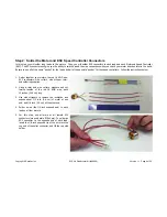
1.
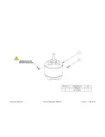
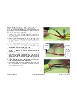
Gather together your motors, the red 16 AWG wire,
EC3 connectors, wire cutters, wire stripper, ruler,
and soldering supplies.
2.
Using a ruler and wire cutters, measure and cut
twelve lengths of the red 16 AWG wire, each
12 inches (30.5 cm) long.
3.
Use wire strippers to remove the insulation and
expose about 1/4 inch (0.6 cm) of metal at one
end, and 1/8 inch (0.3 cm) at the other end.
4.
Solder a wire (the 1/4-inch exposed end) to each
lead on all four motors.
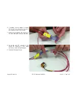
5.
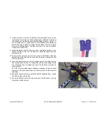
For this step, use all male or all female EC3
connectors (we used male EC3s here). To solder an
EC3 connector to the opposite end of each lead,
insert the 1/8-inch exposed tip of the wire into the
cup end of the bullet connector, and fill the cup with
solder.


