4
March
2005
8335-A2-GZ40-60
To order a paper copy of a Paradyne document, or to speak with a sales
representative, please call 1-727-530-2000.
Installation Overview
Installation and configuration of the ATM Line Card consists of:
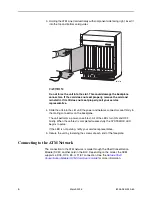
Installing the card in the BLC.
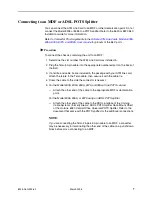
Connecting to a Main Distribution Frame (MDF).
Connecting to the DS3, OC3, E3, or T1/E1 uplink.
Providing initial unit identity information or changing existing identity
information.
Configuring your unit using the Configuration Edit menus.
Be sure to register your warranty at
www.paradyne.com/warranty
.
Planning the Installation
Review the following list to help plan for the installation.
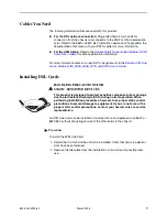
❑
Obtain the applicable cables; refer to
Cables You Need
on page 5
.
❑
Make sure the chassis is installed and power is supplied to it.
❑
After the ATM Line Card is installed, there are configuration procedures that
must be performed before you can begin to use it. Refer to the
Hotwire ATM
Line Cards, Models 8335, 8355, 8365, 8375, and 8385, User’s Guide
for
detailed configuration procedures.
6390-A2-GN10
Hotwire ReachDSL Modem, Model 6390 with Inline Phone Filter,
Installation Instructions
8000-A2-GB22
Hotwire Management Communications Controller (MCC) Card,
IP Conservative, User’s Guide
8021-A2-GB20
Hotwire Shelf Concentration Module (SCM) Card User’s Guide
8021-A2-GZ40
Hotwire Shelf Concentration Module (SCM) Card Installation
Instructions
8620-A2-GN20
8620 Broadband Loop Carrier Installation Guide
8820-A2-GN20
8820 Broadband Loop Carrier Installation Guide
Document Number Document Title

