COMSPHERE 3550 Series Data Service Units
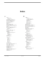
Index-6
July 1999
3550-A2-GB20-40
leads
external, 4-19
changing, 4-19
displaying, 4-19
reporting external changes to NMS, 4-20
states, 4-20
LED, light-emitting diode, 1-2
LEDs, 4-19
line
communication
DSU, 1-6
V.32 DBM, 1-7
speeds, 1-3
Link Delay, 5-11
link-level network addressing, 3-10
LinkConfig, 5-10
LL, 4-9
LL by DTE, 5-19
local loopback, 4-9
loopback, 4-9
bilateral, 2-12, 3-12, 4-10
digital, 2-12, 3-12, 4-10
DTE, 2-12, 3-12, 4-10
local, 2-12, 3-12, 4-9
remote digital, 2-12, 3-12, 4-10
loopbacks, 4-9
Lpbk, 4-9
LSD, status indicator, C-2
LSD Lead, 5-18
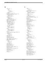
M
management control, 1-2
manual backup, 4-8
Max, C-6
Menu, 4-12
mode, 4-12, 5-5
subbranch, 5-5
menu
selections, backup branch, 4-8
structure, 4-4
tree, A-1
Menu Mode
disabled, 4
enabled, 2
messages
branch, 4-20
control panel, C-1, C-3
device health and status, C-3
error, C-9
TDM/Flex, C-11
expanded health and status, C-6
format, C-3
health and status, C-3
progress, C-8
command, C-8
dial backup, C-8
subnetwork health and status, C-7
mode
DBM, C-3
Dial Backup, 4-7
External Backup, 4-7
Idle, 4-7
Menu, 5-5
Standby, 4-7
Model 3550
dial (PSTN) network connection, 2-6
dial network pin assignments, D-2
digital network pin assignments, D-2
NMS connection, figure, 2-6
Model 3551
installation, and circuit pack lock, 3-6
jumper straps, 3-4
rear connector plate, D-4
switch and jumper locations, 3-3
modulation, 1-7
MPTC, 4-13
M-PtSymPrt, 5-11
MPTT, 4-13
Msg Clamp, 5-6
Msgs, 4-20
MultiCall, 4-7, 5-22
multiplexing, 1-3
multipoint rate adaption, 5-11
multispeed operation, 1-1
MUX
(Port) configuration options, 5-23
(Setup) configuration options, 5-23
CommunicFail message, C-5
Device Fail message, C-5
Device Failure, C-7
Failure alarm, C-2
message, C-7
MUX Funct, 5-23
N
NetL, DSU test, C-4
network
address, 4-18
addressing, link-level, 3-10
compatibility, DSU, 1-6
connection, 3-8
DDS, 3-9
dial, 3-8
NMS, 3-8
connections, 2-5
DDS (or LADS), 2-7
dial, 2-6
DSU test, initiator, C-4
interface
DDS, 1-6
switched, 1-7
loopback, DSU test message, C-4
Next, 5-5
Summary of Contents for COMSPHERE 3550 Series
Page 4: ...COMSPHERE 3550 Series Data Service Units C July 1999 3550 A2 GB20 40 Notices...
Page 12: ...COMSPHERE 3550 Series Data Service Units vi July 1999 3550 A2 GB20 40...
Page 68: ...COMSPHERE 3550 Series Data Service Units 4 22 July 1999 3550 A2 GB20 40...
Page 98: ...COMSPHERE 3550 Series Data Service Units 5 30 July 1999 3550 A2 GB20 40...
Page 100: ...COMSPHERE 3550 Series Data Service Units A 2 July 1999 3550 A2 GB20 40...
Page 101: ...DSU Menu A 3 3550 A2 GB20 40 July 1999...
Page 108: ...COMSPHERE 3550 Series Data Service Units B 6 July 1999 3550 A2 GB20 40...
Page 122: ...COMSPHERE 3550 Series Data Service Units C 14 July 1999 3550 A2 GB20 40...
Page 129: ...Pin Assignments D 7 3550 A2 GB20 40 July 1999 Figure D 5 EIA 232 D Crossover Cable 4951 035F...
Page 134: ...COMSPHERE 3550 Series Data Service Units E 4 July 1999 3550 A2 GB20 40...


