background image

1. Introduction

1-6


November 

2004

8820-A2-GN20-80

Summary of Contents for 8820

Page 1: ...8820 Broadband Access Concentrator Installation Guide Document No 8820 A2 GN20 80 November 2004...

Page 2: ...resentative service representative or distributor directly for any help needed For additional information concerning warranty sales service repair installation documentation training distributor locat...

Page 3: ...DING WITHOUT LIMITATION IMPLIED WARRANTIES OF MERCHANTABILITY FITNESS FOR A PARTICULAR PURPOSE AND NON INFRINGEMENT Some states or other jurisdictions do not allow the exclusion of implied warranties...

Page 4: ...ically isolated from an AC source or provided by batteries The DC source is to have one pole reliably connected to earth Connect the earthing grounding wire to the protective earthing grounding lug co...

Page 5: ...equirements as prescribed in the appropriate Terminal Equipment Technical Requirements document s The Department does not guarantee the equipment will operate to the user s satisfaction Before install...

Page 6: ...ite at www paradyne com Select Library Technical Manuals CE Declarations of Conformity Japan Class A ITE This is a Class A product based on the standard of the Voluntary Control Council for interferen...

Page 7: ...Configuration 2 6 Positioning the Mounting Brackets 2 6 Changing the Setback Position of the Mounting Brackets 2 7 Installation into a 19 Inch or 23 Inch Rack 2 8 Installation into a Rack without Thre...

Page 8: ...onnecting the Alarm Out Port to a CO Alarm System 4 4 Connecting an SCP Card to an SNMP Management System 4 5 Connecting an MCP to an SNMP Management System 4 5 Connecting to the IPC Ethernet Hubs or...

Page 9: ...tor A 2 Serial SCM and SCP Serial Connector A 2 Alarm In Connector A 3 Alarm Out Connector A 3 MCP LAN and SCP LAN Connectors A 4 HUB 1 and HUB 2 LAN Connectors A 4 LAN SLOT 10BaseT Connectors A 5 Tel...

Page 10: ...Contents iv November 2004 8820 A2 GN20 80...

Page 11: ...20 BAC how to install it and how to install cards into the chassis Chapter 3 Cabling Line Card Tip and Ring Describes how to install the cables that provide tip and ring connections for the line cards...

Page 12: ...GZ40 Hotwire Shelf Concentration Module SCM Card Installation Instructions 8303 A2 GZ40 Hotwire 8303 8304 IDSL Cards Installation Instructions 8312 A2 GZ40 Hotwire 8312 8314 MVL and ReachDSL MVL Cards...

Page 13: ...ination Unit with DSX 1 Interface User s Guide 8784 A2 GZ40 Hotwire 8784 TDM SDSL Termination Unit with DSX 1 Interface Installation Instructions 8786 A2 GB20 Hotwire 8786 TDM SDSL Termination Unit wi...

Page 14: ...About This Guide viii November 2004 8820 A2 GN20 80...

Page 15: ...f the BAC there are two configurations SCP card based A Shelf Concentration and Processing SCP card is installed in Slot A or B to provide the management functions of the MCP and the aggregation funct...

Page 16: ...lacement for both the MCP card and the SCM card MCP card Administers and provides diagnostic connectivity to the line cards The MCP acts as a mid level manager and works in conjunction with an SNMP ne...

Page 17: ...ket SDSL CAP card with ATM uplink that interoperates with the 6341 and 6342 SDSL Routers 8355 24 port ReachDSL card that interoperates with the Hotwire 6390 ReachDSL modem 8365 12 port ATM Asymmetric...

Page 18: ...e either through the two PEMs on the front or through the screw terminals on the rear of the chassis as long as both are not used at once However for ease of maintenance rear connection is recommended...

Page 19: ...te the status of important functions see LEDs in Chapter 6 Troubleshooting Hot Swappable Cards The MCP backup SCP card and line cards can be installed and removed from the chassis without service disr...

Page 20: ...1 Introduction 1 6 November 2004 8820 A2 GN20 80...

Page 21: ...y heat generating equipment in the rack allow at least 4 inches 10 cm between the back of the rack and a solid wall Otherwise allow at least 6 inches 15 cm Take care that other equipment does not blow...

Page 22: ...onnection to a CO alarm system if required 8 pin shielded CAT5 modular cable is required for connection to the DSL 10 100BaseT Ethernet ports You will need this cable for each RADSL IDSL Packet SDSL R...

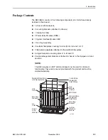
Page 23: ...These cards are not provided with this product and must be ordered separately 04 17545 Multislot Filler Plates with Receptacles MCP Card Fan Module inside System Interface Module Power Entry Modules D...

Page 24: ...nted connectors 4 small cable bushings 5 wire ring tongue terminals for use with the power source wires 18 cable ties to attach the Tip and Ring cables to line cards should locking pivot brackets not...

Page 25: ...ATTHE SOURCE BEFORE REMOVING OR INSTALLINGTHIS PWR ENTRY MODULE 48V RTN 48V NEG POWER ENTRY MODULE LEFT UNIT LINE A RIGHT UNIT LINE B WARNING POWER MUST BE DISCONNECTED ATTHE SOURCE BEFORE REMOVING O...

Page 26: ...use the 12 24 screws and self retaining nuts provided with the chassis Mounting Brackets Configuration The chassis is equipped with reversible mounting brackets installed on the chassis with a 1 inch...

Page 27: ...edure To change the position of the mounting brackets 1 Remove the screws three on each side that hold the mounting brackets to the chassis 2 Reposition the brackets for the desired setback flush 1 in...

Page 28: ...r mounting screws on each side of the rack 2 Use the screwdriver to install two screws loosely enough to allow the bracket keyholes to drop over the screw heads during installation 3 Place the chassis...

Page 29: ...he appropriate locations for the machine screws on the rack 2 Slip a self retaining nut onto each rail hole selected and align the hole of the self retaining nut with the hole in the rail 3 Line up th...

Page 30: ...de the filter upwards until it seats against the foam strip located on the backplane NOTE When oriented properly the vertical arrows on the front and rear edges of the filter point up 3 Replace the ve...

Page 31: ...rear power access connections Rear power access is recommended due to ease of installation Selecting the rear power access method also eliminates the need for routing large 8 gauge wires to the PEMs...

Page 32: ...MCT 8200 2 Remove the PEM to be wired from the chassis by unfastening the two screws from the PEM faceplate Save these screws since they will be needed when the wired PEM is reinstalled into the chass...

Page 33: ...ard and perpendicular to the faceplate 5 Feed and dress the power wires through the notched holes at the top of the PEM s faceplate 6 Slightly spread open the split cable bushings and slip them over t...

Page 34: ...n disconnected at the source When installing or servicing rear access power connections never remove both metal covers at the same time to avoid exposure to 48 or 60 VDC potentials NOTE Both PWR A and...

Page 35: ...tom of the chassis or the metal cover 4 Route the rear access power wires either up through the bottom of the chassis or straight through the cover plate 5 Remove the two M4 Phillips head screws insta...

Page 36: ...damage due to electrostatic discharge ESD during normal operation When performing installation procedures however take proper static control precautions to prevent damage to equipment If you are not s...

Page 37: ...ess being assigned to all slots Slot Is Shipped with And Can Accept These Cards For Installation Instructions See 1 7 10 16 Two multislot filler plates left covering Slots 1 7 and right covering Slots...

Page 38: ...Installation on page 2 27 6 Secure the card by fastening the screws on each end of the faceplate This is required to maintain proper gasket pressure on the faceplate as well as proper air flow ALARMS...

Page 39: ...he LEDs turn ON and OFF briefly When the self test is completed successfully the SYSTEM OK LED will turn ON Make sure the OK SYSTEM indicator on the MCP faceplate is ON blinking green 5 Secure the MCP...

Page 40: ...stment and Reinstallation The BAC comes with the following filler plates installed Two single 0 8 inch 2 03 cm wide EMI gasketed filler plates for Slots 9 and 18 Two single 1 inch 2 54 cm wide EMI gas...

Page 41: ...d 18 Remove the single EMI gasketed filler plate Store for future use Slots 8 and 17 Remove the single filler plate with receptacle and install EMI gasketed filler plate ALARMS Major Minor Fan B A POW...

Page 42: ...alling cards in Slots 1 8 or 10 17 remove the appropriate multislot filler plate use tabs provided 2 From the side of the multislot filler plate without the EMI gaskets break away as many panels as ne...

Page 43: ...EMI gaskets on the left side of the multislot filler plate by applying slight pressure to the left 7 Replace the screws in the multislot filler plate to fasten it to the chassis ALARMS Major Minor Fan...

Page 44: ...Slot 9 Remove the single EMI gasketed filler plate from Slot 9 and store it for possible later use Proceed with Step 2 on page 2 25 Installing Line Cards into Slots 8 and 18 If you are installing onl...

Page 45: ...STEM OK indicator on the line card faceplate is blinking green For a more detailed explanation of LEDs on the line card refer to the appropriate line card documentation 5 Secure the line card by tight...

Page 46: ...tors on the backplane Then press in on the latches until the card is fully seated 4 Verify that the OK SYSTEM indicator on the card s faceplate is blinking green 5 Secure the card by fastening the scr...

Page 47: ...that the SYSTEM OK LED is cycling off and on Verify that the SYSTEM OK LEDs on any line cards are cycling off and on If these LEDs fail to appear as described see Troubleshooting Table and LEDs in Ch...

Page 48: ...2 Installation 2 28 November 2004 8820 A2 GN20 80...

Page 49: ...the chassis using the cable ties provided or you can use the locking pivot brackets provided See Connecting a Line Card Using Cable Ties or Installing Locking Pivot Brackets on page 3 2 EMI NOTICE In...

Page 50: ...the Phillips pan head screw that you replaced in Step 1 on the right side of the connector 5 Make sure the other end of the cable is connected to the appropriate POTS splitter shelf MDF or demarcatio...

Page 51: ...3 Align the two connectors 4 Rotate the connector until it is fully seated 5 Tighten the captive screw on the top of the cable s connector to secure it to the insert mounted on the rear cover 6 Repeat...

Page 52: ...e screws three on each from the cable management brackets and then remove the cable management brackets from the chassis Reposition the brackets so that the open slots face the rear 2 Reinstall the sc...

Page 53: ...ft 2 Taking one of the split cable bushings open the bushing and slip it over the cable on the outside of the cable management bracket 3 Slide and snap the bushing into the slotted hole of the cable m...

Page 54: ...3 Cabling Line Card Tip and Ring 3 6 November 2004 8820 A2 GN20 80...

Page 55: ...cting Clock Sources to Clock A and Clock B on page 4 2 Serial SCM See Connecting an SCP Card to a Terminal or PC on page 4 4 Serial MCP See Connecting an MCP Card to a Terminal or PC on page 4 2 Alarm...

Page 56: ...both connectors 2 Connect the other end of the cable to the BITS clocking source Connecting an MCP Card to a Terminal or PC Procedure To connect an MCP card to a terminal or PC 1 Connect the serial c...

Page 57: ...ode only For example ATQ2 Set the modem to ignore Data Terminal Ready DTR For example AT D0 Procedure To connect the 8820 BAC to a dial up modem 1 Plug a serial cable into the SERIAL MCP port of the c...

Page 58: ...Bits 1 Flow Control None Connecting the Alarm Out Port to a CO Alarm System The following procedure is optional Follow this procedure only if you want to connect to a CO alarm system See Alarm Out Co...

Page 59: ...cted to the SNMP management system network Connecting an MCP to an SNMP Management System Procedure To connect an MCP card to an SNMP management system or for Telnet access to the MCP card 1 Plug an 8...

Page 60: ...in Slot 2 etc 2 Dress the cable s to the right and through the cable retainer 3 Plug the other end of the cable into your IPC Ethernet hub connector or switch Hot Insertion or Removal of the SIM If t...

Page 61: ...Connecting an SCP Card to a Terminal or PC on page 5 4 Alarm In See Connecting the Alarm In Port to an External Alarm on page 5 5 Alarm Out See Connecting Alarm Out to the CO Alarm System on page 5 6...

Page 62: ...the BITS clocking source Connecting an MCP Card to a Terminal or PC Procedure To connect an MCP card to a terminal or PC 1 Connect the serial cable with 8 pin modular plugs on each end provided with t...

Page 63: ...ate mode only For example ATQ2 Set the modem to ignore Data Terminal Ready DTR For example AT D0 Procedure To connect the 8820 BAC to a dial up modem 1 Plug a serial cable into the MCP Serial port of...

Page 64: ...e 9600 Data Bits 8 Parity No Parity Stop Bits 1 Flow Control None Connecting to a Modem for Remote Management with SCP Card Before connecting the 8820 BAC to a standard AT dial up modem configure the...

Page 65: ...ote locations External fan failures External power failures in a Remote Terminal RT See Alarm In Connector in Appendix A Pinouts Procedure To connect a device to the 8820 BAC s Alarm IN port 1 Plug an...

Page 66: ...tem inputs Connecting an MCP to an SNMP Management System Procedure To connect an MCP card to an SNMP management system or for Telnet access to the MCP card 1 Plug an 8 pin modular cable into LAN Slot...

Page 67: ...he SNMP management system network Connecting the Hub 1 and Hub 2 LAN Ports The Hub 1 and Hub 2 LAN ports provide a NEBS compliant hub for applications that require connecting external devices though t...

Page 68: ...on See the 8620 and 8820 Broadband Access Concentrators TL1 Interface Reference for more information Hot Insertion or Removal of the SIM If the port card Ethernet interfaces are not being used it is p...

Page 69: ...appropriate electrician SYSTEM ALM LED is ON and line card is inoperative in Slot n For an SCP card based chassis 1 Using the Status Alarms screen of the web interface determine what alarms have been...

Page 70: ...sent on any of the cards in the chassis The card with alarm conditions will also have its Alarm LED lit No major alarms Minor Alarm Yellow Off Minor alarm present on any of the cards or Power Alarm pr...

Page 71: ...CP card is installed the CLOCK A and CLOCK B connectors may be used for system clocking They have the following pin assignments Pin Number Use 1 Not used 2 Not used 3 Not used 4 Signal 5 Signal 6 Not...

Page 72: ...SCM connector 8820 S1 902 or SCP SERIAL connector 8820 S1 905 is a DCE type connection with the following pin assignments Pin Number Use 1 Reserved 2 Reserved 3 Reserved 4 Signal Ground 5 Receive Data...

Page 73: ...minor alarms to a CO alarm system The following table lists the pin assignments for the 8 pin jack Pin Number Use 1 Alarm Sense 1 2 Alarm Sense 1 3 Reserved 4 Reserved 5 Reserved 6 Reserved 7 Alarm Se...

Page 74: ...LAN Connectors The 8 pin interfaces for the HUB 1 LAN and HUB 2 LAN 10BaseT connections 8820 S1 905 have the following pin assignments Pin Number Use 1 TX Data 2 TX Data 3 RX Data 4 Reserved 5 Reserv...

Page 75: ...10BaseT Connectors The 8 pin interfaces for the LAN 10BaseT connections 8820 S1 902 have the following pin assignments Pin Number Use 1 TX Data 2 TX Data 3 RX Data 4 Reserved 5 Reserved 6 RX Data 7 Re...

Page 76: ...inouts for DSL Ports for Each Slot NOTE The above table lists the port assignments of the slots and their respective connectors for 25 ports DSL port cards with less than 25 ports have their ports ass...

Page 77: ...CP card and the MCP is used to convert the 8 pin modular serial interface to a standard DB9 interface which can then be connected to a laptop computer The following table lists the pin assignments 8 P...

Page 78: ...A Pinouts A 8 November 2004 8820 A2 GN20 80...

Page 79: ...a frame Dimensions Height 24 5 inches or 14U 62 23 cm Width 17 20 inches 43 69 cm with 19 inch mounting brackets Depth 11 50 inches 29 21 cm with no cables 12 00 inches 30 48 cm with rear cables 14 70...

Page 80: ...dity 5 to 95 noncondensing Storage Temperature 40 F to 158 F 40 C to 70 C Shock and vibration sufficient to withstand normal shipping Ambient Temperature 40 to 149 F 40 to 65 C Relative Humidity 5 to...

Page 81: ...tions require the use of 8 AWG standard wire The chassis operates from a standard CO 48 VDC power supply 42 0 to 57 0 VDC The chassis operates from a standard CO 48 or 60 VDC power supply 40 to 72 0 V...

Page 82: ...B Technical Specifications B 4 November 2004 8820 A2 GN20 80...

Page 83: ...2 8 in rack without threaded screwholes 2 9 Clock A and Clock B 4 2 5 2 pinouts A 1 CO alarm contacts 1 5 CO alarm system 4 4 configuration 1 2 mounting brackets 2 6 connecting a line card 3 2 Alarm I...

Page 84: ...4 pinouts A 4 MCP Serial pinouts A 2 modem 4 3 5 3 5 4 mounting brackets 2 6 configurations 2 6 positioning 2 6 2 7 setback 2 7 MTAU testing 5 8 N NEBS 1 5 B 1 Notice to Users of the Canadian Telephon...

Page 85: ...2 Serial SCM connector A 2 pinouts A 2 setback position of mounting brackets 2 7 SIM 4 6 5 8 site 2 1 SNMP 4 5 5 6 5 7 SNMP connection 4 5 5 6 5 7 Software and Firmware License Agreement B split cabl...

Page 86: ...Index IN 4 November 2004 8820 A2 GN20 80...

Reviews: