


Page 7
Overview
Chapter 2: Overview
This section provides an overview of the Paradox PCS200 Communicator
Module. It covers technical specifications, light-emitting diode (LED)
functionality, and an overview of the PCS200 system components.
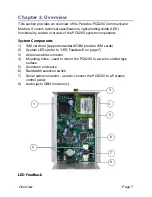
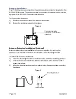
System Components
1)
SIM card slot (supports standard GSM provider SIM cards)
2) System LEDs (refer to “LED Feedback” on page 7)
3) Antenna cable connector
4) Mounting holes - used to mount the PCS200 to a wall or similar type
surface
5) Aluminum
enclosure
6) Bandwidth selection switch
7)
Serial cable connector - used to connect the PCS200 to a Paradox
control panel
8) Audio jack (GSM mode only)
LED Feedback
2
8
7
4
6
1
3
5


