


Chapter 5: System Configuration
31
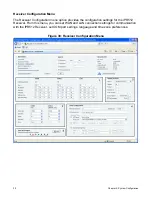
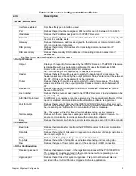
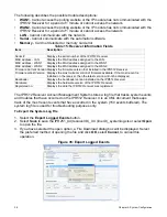
Table 11: Receiver Configuration Menu Fields
Item
Description
1 - WAN1, WAN2, LAN
Interface enabled
Specifies the type of interface used.
Port
Defines the port number assigned. Port numbers can be between 0 to 65535.
IP address
Defines the IP address assigned to the IPR512 Receiver.
Netmask
Defines the 32-bit mask used to divide an IP address into subnets and specify the
network’s available hosts.
Gateway
Defines the Gateway address assigned to the network for communication with
other computers or networks.
DNS primary
Defines the primary DNS address for translating domain names into IP
addresses.
DNS secondary
Defines the secondary DNS address for translating domain names into IP
addresses.
Note: Speak to your network administrator to obtain these values.
2 - Output Protocol
Output
Displays the reporting format used by the IPR512 Receiver. The IPR512 Receiver
is compatible with any automation software that uses the Radionics 6500,
Ademco 685, and Sur-Gard MLR2-DG standard.
Note: SIA reporting is not supported by the Ademco 685 protocol.
Header
Defines the byte that will be used to signify the beginning of a message. The
header values are defined by the output protocol. Values entered can be between
00 - FF. If 00 is set, the header will not be included.
Trailer
Defines the byte that will be used to signify the end of a message. The trailer
values are defined by the output protocol. Values entered can be between 01 -
FF.
Receiver ID
Defines the unique ID assigned to the IPR512 Receiver. Receiver ID can be
between 01 and 99.
Line number
Defines the line number assigned to the IPR512 Receiver. Line numbers can be
between 01 - 34.
ACK/NACK protocol
An affirmative or negative response received by the automation software. If this
option is enabled, communication with automation software is supervised.
Wait for ACK
Defines the amount of time that the IPR512 GPRS/IP Monitoring Receiver will
wait for an acknowledgement from the monitoring station’s automation software
before sending an “Automation Communication Failure” message.
Note: The system will wait for three attempts before sending the error message.
Test message
Defines whether a presence message is sent at a defined period intervals to
ensure communication remains active with automation software.
Every
Defines the interval at which the periodic test message is sent (00 to 99 seconds).
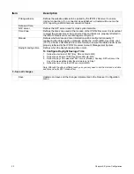
3 - COM Ports
Baud rate
Defines the data transfer rate from the IPR512 Receiver to the communication
link (RS-232).
Data bits
Defines the number of bits used to represent one character of data (most forms of
data require eight bits).
Parity
Defines whether parity is being used for error detection.
Stop bits
Defines the number of stop bits used between sending and receiving data.
Flow
Defines the type of flow control used for the serial port COM1 connection.
4 - Other Configuration
Receiver password
Defines the password used for the registration process of the PCS100/IP100.
This password must be entered in the control panel when registering a new
PCS100/IP100 to the IPR512 Receiver.
Upgrade port
Defines the port used for system upgrades. This port number must also be
provided in the In-Field Paradox Upgrade Software application.
Summary of Contents for IPR512
Page 1: ...IPR512 GPRS IP Monitoring Receiver V1 2 Operations Manual...
Page 63: ......


