Upgrading the Firmware
41
Black/White LCD Mini-Touch Panels
.
8.
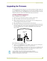
Using the new EPROM, match up the socket holes to their respective prong and match the
notches to the correct direction for the new chip.
9.
Insert all of the prongs simultaneously until each is firmly resting in its socket hole and the
entire chip is securely connected to its base.
10.
Rotate the circuit card back to the original position and place it in the touch panel housing.
11.
Plug the 4-pin AXlink connector back into the touch panel for approximately 1 minute. Once
you can confirm that the panel is receiving power, remove the connector, align the screw hole
and insert the Phillips-head screw and tighten.
12.
Replace the housing on the touch panel and align the screw holes. Insert the seven Phillips-
head screws and tighten.
13.
Plug all connectors back into the touch panel.
14.
Re-install the unit to its appropriate mounting surface.
Insert the EPROM with the notches facing the correct direction. During the
replacement process, cables may be pulled from their connections and should be re-
checked to confirm they are securely connected.


