background image

PANDUIT TDP4*H

GMTDPH-MAN

Page 2-8

Section 2: Installation

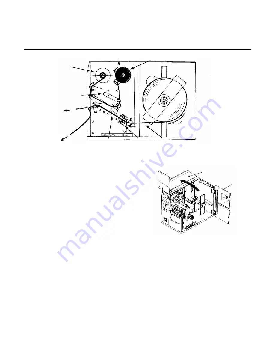
1. Open the Top Access Door by swinging it up and 

to the left and the Side Access Door by swinging it
toward the rear of the printer.

2. Open the Print Head by rotating the Head Latch

toward the rear of the printer. The Print Head is
spring-loaded and will automatically open as soon
as the Head Latch is disengaged.

3. Locate the extra ribbon core supplied with the

printer. Place the core on the Ribbon Rewind
spindle, pushing it all the way to the inside of the
spindle. Note that the new empty core of each
subsequent roll becomes the next rewind core.

4. Load the ribbon onto the Ribbon Supply Spindle, also pushing it all the way to the inside of the

spindle. the dull side of the ribbon should be facing down as it travels through the Print Head
Assembly.

5. Feed the leader portion of the ribbon through the Print Head Assembly and up to the Ribbon Rewind

spindle following the routing shown in the diagram.

6. Load the ribbon behind and over the top of the Ribbon Rewind spindle and tape it to the Extra Ribbon

Core. Make sure it matches the ribbon path shown in the diagram.

7. Manually turn the Rewind spindle to wrap the ribbon onto the core one to two turns to secure it.

Loading the Ribbon

Ribbon Roll

Ribbon Path

Ribbon Rewind
Spindle

Head Latch

Dispensed
Label

Label Backing

Sensor
Assembly

Label
Hold
Down

Label Patch

Top Access Door

Side Access Door

Summary of Contents for TDP43H

Page 1: ...TDP42H TDP43H TDP46H Thermal Transfer Printer OPERATOR MANUAL GMTDPH MAN...

Page 2: ...p Identification Products Division 1819 Atlanta Hwy Cumming GA 30040 1069 Phone 800 777 3300 Fax 708 532 1811 email id support panduit com website www panduit com Copyright PANDUIT Corp 2004 All Right...

Page 3: ...s 3 7 Potentiometer Adjustments 3 8 LCD Panel Printer Configuration 3 10 Section 4 Cleaning and Maintenance Introduction 4 1 Adjusting the Print Quality 4 1 Cleaning the Print Head Platen and Rollers...

Page 4: ...6 2 IEEE1284 Parallel Interface 6 3 RS232 Serial Interface 6 5 Universal Serial Bus USB Interface 6 8 Local Area Network LAN Optional Interface 6 8 BiDirectional communications 6 8 Section 7 Optional...

Page 5: ...ces between it and other RISC printers are the allowable values representing the print positions on the label These values are specified in dots and will vary depending upon the resolution of the prin...

Page 6: ...28 in 30mm 5 0 in 125 mm Roll or Fan Fold Die Cut Labels Thermally Sensitive 0 008 in 0 21 mm 8 6 in 220 mm 3 in 76 2 mm 14 0 in 356 mm Print Module Dot Size Resolution Maximum Print Width Maximum Pr...

Page 7: ...el Front Panel Front Panel Front Panel Offset Pitch Display Parallel IEEE1284 Standard Serial RS232C 9600 to 57600 bps Standard RS422 485 9600 to 57600 bps Optional Ready Busy or X On X Off Flow Contr...

Page 8: ...W x 36 dots H 44 dots W x 66 dots H 60 dots W x 72 dots H 15 dots W x 22 dots H 30 dots W x 36 dots H WB 18 dots W x 30 dots H 28 dots W x 52 dots H 48 dots W x 48 dots H Univers Condensed Bold 48 dot...

Page 9: ...Maxicode PDF417 Micro PDF Truncated PDF QR Code 1 2 1 3 2 5 User Programmable 4 to 999 dots User Programmable 0 90 180 and 270 Rotation Sequential numbering of both numerics and bar codes RAM storage...

Page 10: ...Temperature Storage Humidity Operating Humidity Electrostatic Discharge Safety RFI EMI 10 4 in 265 mm 17 1 in 435 mm 13 4 in 341 mm 39 7 lb 18 0 Kg 115 220 VAC 10 50 60 Hz 1 130W Operating 24W Idle 4...

Page 11: ...und LABEL REWINDER External Option that rewinds labels onto a roll after they are printed LABEL CUTTER An attachment allowing labels to be cut at specified intervals controlled through programming COA...

Page 12: ...PANDUIT TDP4 H GMTDPH MAN Page 1 8 Section 1 Overview Notes...

Page 13: ...ers and to get started as quickly as possible It is recommended to read each chapter in this manual before the installation of the use of the printers The following information is provided in this sec...

Page 14: ...Remove the accessory items from their protective containers If the printer has been stored in a cold environment allow it to reach room temperature before powering it on Set the printer on a solid fl...

Page 15: ...or terminal The maximum distance for RS232 cables is 35 feet and six feet for IEEE1284 Parallel cables Cables can be purchased locally and their configuration will depend upon the host system being u...

Page 16: ...ction 2 Installation Power Switch Platen Head Latch Print Head Label Guide Label Supply Spindle Label Roll Retainer Label Hold Down Dip Switch Cover LCD Display Top Access Door Ribbon Rewind Spindle R...

Page 17: ...y by pushing the Head Latch toward the rear of the printer The Print Head assembly is spring loaded and will automatically open as soon as the Head Latch is disengaged 3 Loosen the Label Edge Guide an...

Page 18: ...bel Guide and through the Sensor Assembly 8 Open the Label Hold Down by squeezing the green tab and the release tab together The Label Hold Down is spring loaded and will open automatically when the l...

Page 19: ...maximum print width may cause excess head wear due to the label edge See page 2 9 for precautions 12 If the ribbon is already loaded close the Print Head by rotating the black Head Latch toward the fr...

Page 20: ...re 4 Load the ribbon onto the Ribbon Supply Spindle also pushing it all the way to the inside of the spindle the dull side of the ribbon should be facing down as it travels through the Print Head Asse...

Page 21: ...you plan to use multiple widths of labels since the damaged portion of the print head caused from edge wear on a more narrow label may affect the printing on a wider label We suggest you plan your pr...

Page 22: ...tion process PRINT Potenitometer to adjust print darkness fine tuning OFFSET Potentiometer to adjust amount of back forward feed for dispenser cutter tear off position 3 75mm PITCH Potentiometer to ad...

Page 23: ...print job by taking the printer off line It can also be used as a Pause function key to stop the printer during the printing process FEED Momentary switch Pressing this key feeds one blank label when...

Page 24: ...ed AC FUSE Input power protection 3A 250V rating INTERFACE SLOT Connector for Plug In Interface Module MEMORY CARD SLOT Connector for optional PCMCIA Memory Card EXT External signal connector AMP 57 6...

Page 25: ...ndexing Sensor RIBBON END SENSOR Detect motion of the Ribbon supply spindle and signals the printer when it is turning HEAD OPEN SENSOR A micro switch that is activated when the head is unlatched LABE...

Page 26: ...PANDUIT TDP4 H GMTDPH MAN Page 2 14 Section 2 Installation Notes...

Page 27: ...lways up To set the switches first power the unit Off then position the DIP switches Finally after placing the switches in the desired positions power the printer back on The switch settings are read...

Page 28: ...Specifications for more information Will select the Status 2 protocol if DSW2 8 is ON PRINTER SET UP Print Mode Selection DSW2 1 Selects between direct thermal printing on thermally sensitive paper an...

Page 29: ...ning Hex Dump Selection DSW2 4 Selects Hex Dump mode see page 3 21 Receive Buffer Selection DSW2 5 Selects the operating mode of the receive buffer See Section 6 Interface Specifications for more info...

Page 30: ...This switch will also affect the settings selected by DSW1 7 and DSW1 8 Backfeed Sequence DSW3 1 DSW3 2 Backfeed is used to correctly position the label for application and then retract the next labe...

Page 31: ...the last printed label for dispensing and retract it before printing the next label The amount of backfeed offset is adjustable External Signal Interface See Section 6 Interface Specifications for inf...

Page 32: ...type level or pulse of the external print synchronizing signal can be selected Repeat Print via External Signal DSW3 8 Allows the applicator to reprint the current label in the print buffer 1 2 3 4 5...

Page 33: ...us Label Sensor Sensor Used Backfeed Enabled External Signals Enabled SOFTWARE DEFAULT SETTINGS The printer stores the software settings upon receipt and uses them until they are again changed by rece...

Page 34: ...ront panel display 6 Press the FEED key to stop the printer 7 To exit the Test Label mode power the printer off and then back on Adjusting the PITCH potentiometer will affect the stop position of the...

Page 35: ...applied to the head for printing It provides a continuous range of adjustment Maximum print darkness is obtained by turning the potentiometer all the way clockwise and a maximum counterclockwise setti...

Page 36: ...powers on in the ONLINE mode The user can access the User Settings using the following procedures Displays the firmware during the initialization The LCD will display the ONLINE status on the top lin...

Page 37: ...print and the highest setting the darkest print 1 Press the Cursor keys to step the cursor to the desired setting 2 Once the correct setting is underlined press the ENTER key to accept the selection a...

Page 38: ...nto the mechanism 2 Once the correct direction is selected pressing the FEED key will accept the setting and advance the cursor to the Offset selection 3 Use the LINE key to step the first digit of th...

Page 39: ...ing the LINE key while simultaneously turning power on The printer will emit one long beep after which the LINE key is released Press FEED This setting determines if a zero is printed with a slash or...

Page 40: ...If you exceed the allowable limit the printer will not accept the setting 1 Use the LINE key to step the counter to the desired setting The display will increment one step for each time the FEED key i...

Page 41: ...the correct date pressing the LINE key will advance the cursor to the two digit Hour position You can scroll through the numbers corresponding to the hour using a 24 hour clock by pressing the LINE a...

Page 42: ...ional expanded memory will be addressed as CC1 in the command streams The CARD selection specifies the optional PCMCIA card as CC1 and the optional Expanded Flash ROM as CC2 The Memory selection speci...

Page 43: ...If Yes was selected the copy process will start 4 Once the copy process is completed press the FEED key to step the display 5 If an error is encountered in the copy process one of the following messa...

Page 44: ...e display will return to the previous selection 3 Press the FEED key to accept the selection If Yes was selected the copy process will start 4 Once the copy process is completed press the FEED key to...

Page 45: ...ou select No the display will return to the previous selection 3 Once the copy process is completed press the FEED key to step the display 4 If an error is encountered in the copy process one of the f...

Page 46: ...nt allows you to manually set the threshold voltage level between the maximum and minimum light levels DIP switch DSW2 2 selects the sensor type If DSW2 2 is in the OFF position the setting will be fo...

Page 47: ...er the sensor and close the Label Lid Record the voltage shown on the top line of the LCD panel The voltage ranges measured should be within the following ranges Backing with label 2 0V to 3 5V Backin...

Page 48: ...uate performance 3 Calculate the starting point voltage using the formula 4 Use the LINE and FEED keys to step the counter to the desired setting The reading will advance to a setting of 4 9 the maxim...

Page 49: ...255 mm 4 Once the desired distance is set press the FEED key to accept the setting and step to the next display FORWARD BACKFEED DISTANCE DEFAULT FORWARD BACKFEED DISTANCE XXXmm This selection allows...

Page 50: ...etting is selected press the FEED key to accept the setting and step to the next display LABEL RE DETECT ENABLE DISABLE This selection allows the user to disable the feeding of a blank label upon powe...

Page 51: ...exception of the LIFE counter may be cleared 4 Use the LINE key to select the desired setting If you only wanted to read the counter value select NO If you want to read the counter and reset it to 0 0...

Page 52: ...key is pressed the label size advances 1 cm until it reaches a maximum width of 26 cm at which point it will wrap to the smallest size of 13 cm 2 Pressing the FEED key accepts the selection and starts...

Page 53: ...TING COMPLETED Displays the firmware during the initialization V 0 5 00 03 00 INITIALIZING To Clear Non Standard protocol codes DSW2 7 is placed in the On position and the printer powered on while sim...

Page 54: ...download process If they are incorrect turn the printer off without pressing the ENTER key and begin the process again HEX DUMP MODE In addition to the Test Print Labels the printer can print the cont...

Page 55: ...ant to find a proper print darkness level based on your particular label and ribbon combination The printed images should not be too light nor should the ink from the ribbon bleed The edges of each im...

Page 56: ...ore often in dusty environments PRINT SPEED The other method of controlling print quality is by controlling the speed at which the label is printed This adjustment is made only on an individual label...

Page 57: ...he Head Latch Lever down and towards the front until it latches in place PANDUIT TDP4 H GMTDPH MAN Page 4 3 Section 4 Cleaning and Maintenance Cleaning the Label Edge Sensors There are two sensors tha...

Page 58: ...ead Latch toward the rear of the printer The Print Head is spring loaded and will automatically open as soon as the Head Latch is disengaged 4 Remove the ribbon from the Ribbon Rewind Spindle if neces...

Page 59: ...ed it will have to be re aligned for proper print quality 8 Carefully attach the new print head to the connectors using caution to make sure the connector keys are correctly positioned and that the co...

Page 60: ...PANDUIT TDP4 H GMTDPH MAN Page 4 6 Section 4 Cleaning and Maintenance Notes...

Page 61: ...Never connect or disconnect interface cables or use a switch box with power applied to either the printer or the host This may cause damage to the interface circuitry and is not covered by warranty 2...

Page 62: ...t Command ESC A and the Stop Command ESC Z If you are using BASIC it may be adding these characters automatically as the line wraps Adding a width statement to your program can help to suppress these...

Page 63: ...ding does not fix the problem try setting switch 1 to ON factory defaults and powering the print server off and then on again if the problem persists the product may be defective INSTALLATION PROBLEMS...

Page 64: ...n the print server and the host computer make sure that the device is set up to allow the print server to send and receive data from the host For example a bridge can be set up to only allow certain t...

Page 65: ...links 3 Short 1 RS232 parameter mismatch Parity Error RS232 Parity Error Error On Line Blinks 3 Short 1 RS232 parameter mismatch Overrun Error RS232 Overrun Error Error On Line Blinks 3 Short 1 RS232...

Page 66: ...PANDUIT TDP4 H GMTDPH MAN Page 5 6 Section 5 Troubleshooting Notes...

Page 67: ...wer To use the IEEE1284 parallel interface to its fullest capability requires that the host also have an IEEE1284 compatible interface and that the two be connected with a cable that meets the IEEE128...

Page 68: ...hand prints all jobs in the order they are received by the printer and the order of printing cannot be changed SINGLE JOB BUFFER The printer receives and prints one job at a time Each job must not exc...

Page 69: ...s interface also operates bi directionally and can report the status of the printer back to the host The receiving buffer will not be able to receive more data again until a Buffer Available condition...

Page 70: ...eference 3 DATA 2 To Printer 21 DATA 2 Return Reference 4 DATA 3 To Printer 22 DATA 3 Return Reference 5 DATA 4 To Printer 23 DATA 4 Return Reference 6 DATA 5 To Printer 24 DATA 5 Return Reference 7 D...

Page 71: ...Error Condition X On X Off Software Flow Control Bi Directional Communication Data Transmission Rate 9600 19200 38400 57600 bps Character Format 1 Start Bit fixed 7 or 8 data bits selectable Odd Even...

Page 72: ...nting e g ribbon out label out 5 To Printer CTS Clear to Send When this line is high the printer assumes that data is ready to be transmitted The printer will not receive data when this line is low If...

Page 73: ...e Buffer Available mark When the printer is taken off line manually it transmits an X Off indicating it cannot accept data When it is placed back on line manually it sends an X On indicating it is aga...

Page 74: ...Local Area Network LAN interface is a Plug In Interface Module that can be installed by the user It requires a driver shipped with each printer that has the interface installed The driver that must be...

Page 75: ...tus A single byte defining the current status of the printer see the Status Byte Definition table Label Remaining Six bytes defining the number of labels remaining in the current print job The range i...

Page 76: ...ommand an ACK 06 hexadecimal is returned if there are no errors and a NAK 16 hexadecimal if a printer error exists Note To provide compatibility with older PANDUIT printers the RS232C interface can be...

Page 77: ...be expanded up to 16MB Type SRAM or Flash ROM Applicable Specifications PCMCIA Version 2 1 JEIDA Version 4 1 Size Up to 4 MB SRAM or 16MB Flash ROM Connector Pins 68 Battery Two years for SRAM type ap...

Page 78: ...two Interface Card Retaining Screws 6 If the new Interface Module is for a serial interface set DSW1 for the proper operation 7 Connect the interface cable to the connector ERROR DESCRIPTION INDICATIO...

Page 79: ...hould be in the ON position and DSW3 2 should be in the OFF position 4 Open the Print Head Assembly and feed the edge of the labels tags into the cutter assembly and out between the label cutters NOTE...

Page 80: ...labels from the backing paper to provide 12 inches of backing free from labels 6 Open the Print Head assembly and feed the backing paper through the print area in the normal manner 7 At the label exit...

Page 81: ...ewind Spindle 4 Feed the lead end of the label stock under the first spindle and onto the Rewind Spindle Feed the stock around the spindle once then replace the metal clamp over the label stock Wind a...

Page 82: ...in the local printer rather than using the system clock It consists of a special clock chip that replaces the EPROM on the main pcb assembly A qualified technician should perform the upgrade as it re...

Page 83: ......

Page 84: ......

Reviews: