PA N D O R A T R A C E R
U S E R A N D I N S TA L L AT I O N MA N UA L
18
19
• To avoid the connection loss because of vibration during driving,
ensure that there is a bit of free length to the wiring, providing enough
sagging.
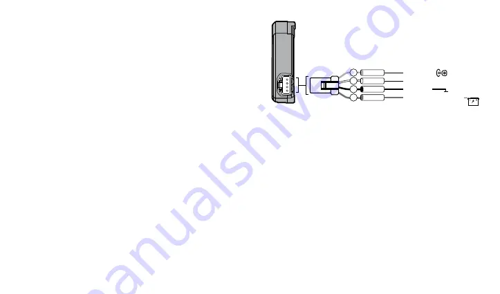
Wires description
№1 I Green I Ignition input
– ignition status. The wire must be
connected to the ignition switch or the wire, where +12V/+24V appears
when the ignition is turned on and does not disappear until the ignition
is turned off. This input is mandatory for connection.
№2 I White I Programmable channel
– control/management
of additional equipment. Pandora NAV BT mobile application and
pandora-on.com online service allow to implement one of the
following settings:
- management over the engine preheater (Webasto/Eberspacher);
- negative status input (hood switch);
- negative output 100 mA (impulse control/ potential control/engine
blocking mode).
№3 I Black I GROUND (-)
– external power supply. It should be
connected to a vehicle grounded spot. This wire must be connected
FIRST during the installation, mandatory for connection.
№4 I Red I POWER 12V/+24V
– external power supply. It
should be connected to the reliable conductor with a constant voltage
of +12V/+24V. Mandatory for connection.
4
Red
+12V/+24V POWER SUPPLY
3
Black
2
White
1
Green
GROUND (-)
Ignition input
Programmable channel
(+)
100mA (-)


