Panasonic YF-0201Z5HGF Operating Instructions Manual Download Page 29

Advanced functions


29

7.5 

Signal-up

It is a function to increase the welding current at the 
preset current incremental rate every time the “Step-up 
shift” input is given.
This sequence is completed when the welding current 
reaches or exceeds the maximum current.

1

Set the DIP switch DPSW1-10 to ON (selecting
“Signal-up”).

2

In the setting mode, set the SOL No., and then set
the current incremental rate. (The set-up conditions
can be set for SOL 

I

 and SOL 

II

 separately.)

3

Press “RUN” key and press the “ENTER/SHIFT” key
three times, then the current accumulated current
incremental rate is displayed.

4

When the welding current (based on the
accumulated current incremental rate) reaches or
exceeds the preset maximum current, the “Signal-up
completion output” (the same output as that for the
step-up completion) is turned on, the “COUNT UP”
lamp of the “STEP-UP CNTR. (MONITOR)” lights,
and the buzzer sounds.

• After that, even if the “step-up shift” input is turned

on, the input is ignored and the operation is
continued at the maximum current while maintaining
the output.

5

If the set value for they current incremental rate is
changed, during the operation, the newly set
incremental rate is added to the current accumulated
current incremental rate.

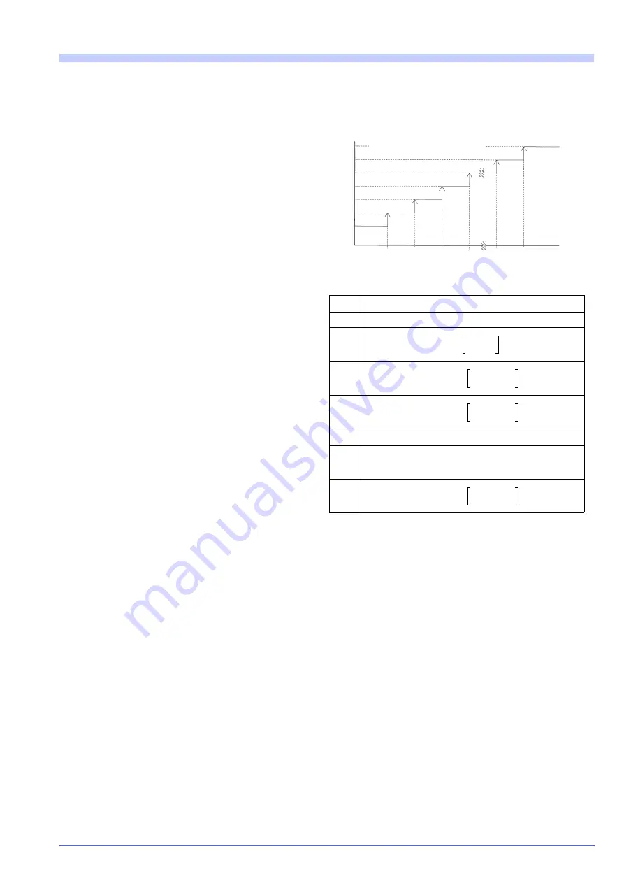
<Signal-up procedure>

Welding current

0

Preset current value

1

Preset current value x 

2

Preset current value x 

3

Preset current value x 

:

n-1

Preset current value x 

n

Preset current value x 

<Note>
  • “S

u

“indicates set value for the signal-up current

incremental rate (0 - 9%).

W

elding cu

rrent

 “Step-up shift” input

1st

2nd 3rd

(n-1)th (n)th

Maximum current (I Max)

1

S

u

100

---------

+

1

S

u

100

---------

2

×

+

1

S

u

100

---------

3

×

+

1

S

u

100

---------

n

1

(

)

×

+

1

S

u

100

---------

n

×

+

Summary of Contents for YF-0201Z5HGF

Page 1: ...oduct please read the instructions carefully and save this manual for future use First of all please read Safety precautions or Safety manual Operating Instructions Controller for resistance welder Model No YF 0201Z5 TSM80344 ...

Page 2: ...or property damage are high Things attention must be paid to The description of this manual is based on the contents as of January 2009 The contents of this manual are subject to change without further notice Danger Warning Caution Introduction This is the operating instructions for YF 0201Z5 series First of all please read and understand this operating instruction for proper and safe operation Fe...

Page 3: ...4 Monitor mode 19 4 2 5 Adjustment and Test run 21 4 3 Starting the welding operation 21 5 Maintenance and inspection 22 5 1 Welding current adjustment 22 5 2 Checking of set data 22 6 Troubleshooting 23 7 Advanced functions 25 7 1 DIP switches DPSW1 DPSW2 settings25 7 2 Functions 26 7 2 1 Functions to be set by DPSW1 26 7 2 2 Functions to be set by DPSW2 27 7 3 Welding counter and Production coun...

Page 4: ...t when not in use 9 Perform periodic checks without fail and repair or replace any damaged parts before using the power source 10 As for coolant water use quality water with few sed iment and 5000 Ω cm or more in resistance 11 Use big enough size of cables and hoses for applied power and pressure Space between electrodes 1 Do not put your hands fingers or arms in the gap between electrodes or part...

Page 5: ...y Model number YF 0201Z5HGF Rated control power Allowable range VAC 100 10 Welding power Allowable range VAC 220 440 selectable 20 to 10 Rated frequency Hz 50 60 auto switching Main circuit switching method Phase control by thyristor Dimensions mm 111 W x 300 D x 338 H Mass kg 5 Accessory Toroidal coil TSMX0007 1 set It is necessary to apply power to both controller and welding machine to operate ...

Page 6: ... Primary constant current control 1 cycle Supply voltage compensation control 1 cycle Initial response 2 cycle 3 Compensation accuracy an error to the full scale current value Constant current control With respect to Supply voltage fluctuation 10 2 or less With respect to Resistance load fluctuation 10 2 or less With respect to Inductive load fluctuation 10 2 or less With respect to Ambient temper...

Page 7: ...lly not to lay the control cables such as input output signal cable for start input near the noise source Note When this machine is newly installed or when the welding machine is replaced with another one set the maximum current value suitable for the applied welding machine Please note the setting of significantly unsuitable maximum current value causes improper current to flow The retention peri...

Page 8: ...actory set to 220 VAC at shipment In case of using it at 440 VAC it is necessary to change the connection of wire 226 to the 8P terminal block at the rear side of this product from 02 to 02 See below figure for detail Do not lay control cables input output signal for starting input near noise source such as the TIG arc welding machine Otherwise the product may malfunction due to the noise WARNING ...

Page 9: ... during operation welding cycle conduction angle welding count and trouble code and various data in the sequence and monitor modes j Data indicator B Shows the data during the operation welding current product count and trouble code the mode during the operation and various data in the sequence and monitor modes k MONITOR lamp Lights when the monitor mode is selected l FULL WAVE lamp Lights when t...

Page 10: ...e the panel display returns to one step before 7 TROUBLE RESET key Use it reset the trouble state 8 TEST key Enables to test the welding sequence The preset sequence is executed when the start input is turned on however the welding current does not flow CH2 is displayed on the data indicator B 9 ADJ key Enables the adjustment Only the pressing operation is performed while the starting input is on ...

Page 11: ...ding counter reset input Production counter reset input Trouble reset input C T input Pressure control output Welding current interlock output 100VAC output connect the power amplifier for proportional control valve Rear side External I O terminals 100 VAC Connected to the control connectors at shipment Note Note Note As SOL I and SOL II are SSR outputs they output 100VAC even in the waiting or st...

Page 12: ...e interlock signal from another machine without moving onto up slope state Step up shift When DIPswitch setting is for Step up mode Input to shift to the next step When DIPswitch setting is for Signal up mode Input to increase the welding current by the preset incremental rate DIP switch DPSW1 10 To select a current incremental method Step up reset or Signal up reset An input to reset the Step up ...

Page 13: ...e signal is turned on when step up or Signal up depending on the current incremental method setting is completed Input the Step up reset input to reset the counter to zero JP2 To select a counter completion output type DIPswitch DPSW1 10 To select a current incremental method Pressure control output Connect the power amplifier when the proportional control valve optional is applied DIP switch 2 1 ...

Page 14: ...a indicator B Operation Lamp indicator Indication 1 Selecting the sequence setting mode Press the MONITOR mode select key MONITOR lamp ON CUR LIMIT lamp ON JOB lamp ON Job No indicator Currently stored job number 2 Setting the MAX CUR Press the ENTER SHIFT key until the MAX CUR lamp is turned on MAX CUR lamp ON Select a number using or key Data indicator B New maximum current Press ENTER SHIFT key...

Page 15: ...hen the Pressure control is OFF Tsd lamp ON lamp ON Data indicator A Currently stored squeeze delay time 4 Setting the pressure control output When the Pressure control is ON Select a number using or key Data indicator A Selected number Press ENTER SHIFT key P SIG OUT lamp OFF X1 upper lamp OFF Tsd lamp ON lamp ON Data indicator A Currently stored squeeze delay time 5 Setting the squeeze delay tim...

Page 16: ...ted number Press ENTER SHIFT key Tc lamp OFF Tw2 lamp ON Data indicator A Currently stored weld time 2 11 Setting the weld time 2 Select a number using or key Data indicator A Selected number Press ENTER SHIFT key Tw2 lamp OFF lamp OFF Data indicator A OFF I2 lamp ON X100 A lamp ON Data indicator B Currently stored welding current 2 12 Setting the Welding current 2 Select a number using or key Dat...

Page 17: ...lected number Press ENTER SHIFT key To lamp OFF lamp OFF PULSATION lamp ON X1 upper lamp ON Data indicator A Currently stored number of pulsations 16 Setting the number of pulsations Select a number using or key Data indicator A Selected number Press ENTER SHIFT key PULSATION lamp OFF X1 upper lamp OFF Data indicator A OFF JOB lamp ON Job No indicator Currently selected job No Operation Lamp indic...

Page 18: ...t key JOB lamp ON START lamp ON Start No indicator 1 2 Selecting the job No for START I Press ENTER SHIFT key START lamp OFF JOB lamp ON Job No indicator Currently stored job number Select a number using or key Job No indicator Selected number Press ENTER SHIFT key JOB lamp OFF Job No indicator OFF START lamp ON 3 Selecting the job No for START II Press Start No indicator 2 Press ENTER SHIFT key S...

Page 19: ...cator B Currently stored current lower limit 4 Setting the current lower limit Select a number using or key Data indicator B Selected number Press ENTER SHIFT key CUR LIMIT lamp OFF Job No indicator OFF lamp OFF Data indicators A B OFF SOL lamp ON SOL No indicator Currently stored SOL number WELD CNTR lamp ON 5 Selecting the SOL No Select a number using or key SOL No indicator Selected number Pres...

Page 20: ...Select a number using or key Data indicator B Selected number Press ENTER SHIFT key lamp OFF X1 lower lamp ON Data indicator B Currently stored welding counter set value for S1 10 Setting the welding counter for step up 1 S1 Select a number using or key Data indicator B Selected number Press ENTER SHIFT key X1 lower lamp OFF Data indicator A ON lamp S 2 Data indicator B Currently stored current in...

Page 21: ... pressing the ENTER SHIFT key See Switching display indication for the order of indication change Note Do not turn off the CONTROL POWER while START input is in ON state If this occurred turn ON the CONTROL POWER within 24 hours If this occurred counter values of monitoring items welding count production count and step up count are reset to the values before turning on the start input therefore in...

Page 22: ...TSMP222 TSM222 ...

Page 23: ...curred At detection Treatment for major troubles 1 Restart impossible Reset by a reset input 2 No output of the hold end signal 3 Trouble output 4 Buzzer goes off 04 Welding power error The welding power is cut off during sequence operation 05 SCR short circuit Current flows during the initial squeeze time At the initial squeeze time 06 Tip sticking When the tip sticking function is selected and t...

Page 24: ...ycles while the initial delay time up slope time weld time 1 cooling time weld time 2 down slope time and hold time are all set to 0 cycle 09 7 Tip sticking Any of the following function is selected together with the tip sticking function Voltage fluctuation compensation control is selected Current off is selected Repetitive welding is selected 09 8 Re welding When the re welding function is selec...

Page 25: ...tart signal is held 2 at start of sequence at start of welding DPSW1 5 Control mode Voltage fluctuation compensation control Constant current control DPSW1 6 Selection of constant current 1 Primary CT Secondary troidal DPSW1 7 Detection of tip sticking Can be done Non DPSW1 8 Re weld mode Can be done Non DPSW1 9 Selection of current off Current stop Sequence stop DPSW1 10 Mode of increase current ...

Page 26: ...is also turned off Self holding at the start of sequence ON Self holding starts at the same time as starting input is accepted and the welding sequence continues even if the starting input is turned off To release self holding state in case of emergency set the DPSW1 9 to OFF side and connect the emergency stop switch to the Sequence stop current off input terminal 5 DPSW1 5 Compensating method Co...

Page 27: ... welding current by the preset incremental rate at every step up input 7 2 2 Functions to be set by DPSW2 1 DPSW2 1 Pressure control Set this switch to ON when the proportional control valve optional is applied In such ase it is necessary to use pressure control unit YX ZZ025 optional 2 DPSW2 2 Checking Make sure to keep this switch OFF It is the switch for manufacturer s checking 3 DPSW2 3 Counte...

Page 28: ...ter value The display for the counters becomes blank 7 4 Step up 1 In the setting mode set the SOL No and then set the current incremental rate and welding count for each step The set up conditions can be set for SOL I and SOL II separately 2 Press RUN key and press the ENTER SHIFT key three times then the current step up number and the remaining welding count of the relevant step are displayed on...

Page 29: ...t the Signal up completion output the same output as that for the step up completion is turned on the COUNT UP lamp of the STEP UP CNTR MONITOR lights and the buzzer sounds After that even if the step up shift input is turned on the input is ignored and the operation is continued at the maximum current while maintaining the output 5 If the set value for they current incremental rate is changed dur...

Page 30: ...side 3 Set the DPSW1 2 DIP switch Contact type Normally open Normally closed Setting Default setting Output type Production counter completion output Step up or signal up counter completion output Setting Default setting TSMP222 DPSW2 DPSW1 JP1 JP2 Front When this product is used with a welding power source that is a primary constant current type or for a single phase DC type it is not possible to...

Page 31: ...oIV Pressure control output Interlock output not given in the Current off mode 1 cycle Off by trouble reset input Off by welding counter reset input Off by production counter reset input Off by step up reset input Off by signal up reset input Hold time end output Trouble output Welding counter completion output Production counter completion output Step up completion output Signal up completion out...

Page 32: ... welding power frequency therefore 1 it may require two cycles of welding power frequency at most to start the sequence after turning on the start input and 2 all start inputs of the desired job No need to be input within the one cycle starting from the acceptance of start signal Do not turn off the CONTROL POWER while START input is in ON state If such a thing occurs turn ON the CONTROL POWER wit...

Page 33: ...8 Circuit diagram Circuit diagram 33 TSMP222 YF 0201Z5HGF Circuit diagram ...

Page 34: ... Power board 4 Transformer UTU21430 Control transformer 5 Transformer UTU21421 Control transformer 6 Switch DS850S00B Power switch 7 Socket plug 12 3B Toroidal coil connecting connector 8 Terminal TS212PLB8P 9 Front cover TSMK0349 Rubber cushion ME25 6 Terminal block cover FEK00001 10 Fuse RT28 32 R015 FLQ1 500V 1A 11 Fuse holder RT28N 32 FUNU30 ...

Page 35: ...tant current compensation I2 A 15 500 X100 Welding current 2 Voltage compensation 0 99 Down slope time Td Cycles 0 20 Hold time TH Cycle 0 99 Off time To Cycles 0 99 1 Number of pulsations Pu Time 0 9 2 Current upper limit Iup 0 20 Current lower limit Idn 0 20 1 When the Off time is set at 0 one spot welding will be executed and it is set to 1 or above repeated welding will be executed 2 When the ...

Page 36: ...999 S0 welding count 0 0 9999 S0 Current incremental rate 0 Fixed S1 welding count 1 0 9999 S1 Current incremental rate 0 25 S2 welding count 2 0 9999 S2 Current incremental rate 0 25 S3 welding count 3 0 9999 S3 Current incremental rate 0 25 S4 welding count 4 0 9999 S4 Current incremental rate 0 25 Signal up Current incremental rate Su 0 9 Set item Symbol Set range Data Job No selection Start I ...

Page 37: ......

Page 38: ...Tangshan new Hi Tech Development Zone 063020 Tangshan Hebei China TEL 86 315 320 6075 86 315 320 6006 FAX 86 315 320 6018 86 315 320 6070 URL pwst panasonic cn 2009 Panasonic Welding Systems Tangshan Co Ltd All rights reserved Printed in China ...

Reviews: