background image

2-2. ALC Mode with SUPER-D2 OFF and ELC Mode

Note:

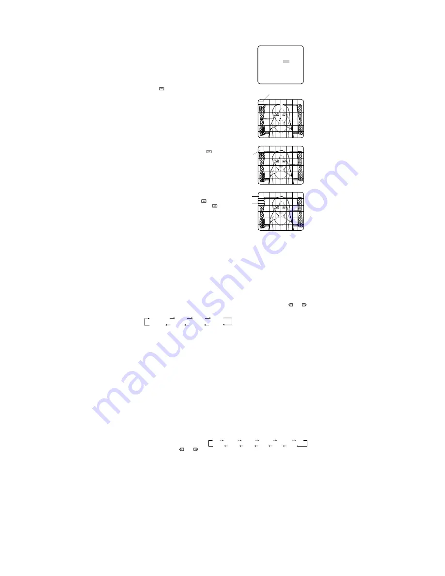
If ELC is selected, set MASK SET according to this procedure.

1. Move the cursor to the SUPER-D2

parameter and select OFF. (When you
select ELC, SUPER-D2 is not avail-
able.) The item MASK SET appears on
the menu.

2. Move the cursor to MASK SET and

press 

. 48 mask areas appear on

the monitor screen. The cursor is blink-
ing in the upper left corner of the
screen.

3. Move the cursor to the area where

backlight is bright and press 

to

mask that area. The mask turns to
white. (When the cursor is moved on
an area that has already been masked,
the mask and cursor start blinking.)

4. Repeat step 3 to mask the desired

area. To cancel masking, move the
cursor to that area and press 

.

5. After masking is completed, press 

for 2 seconds or more. The ALC CONT
menu appears.

6. If you want to change the video output

level (picture contrast), move the “I”
cursor for LEVEL and adjust the level.

Note:

If ON is selected for the SUPER-D2 parameter, a shadow (black line) may appear at

the boundary between the bright and the dim scene. This is a natural phenomenon and
does not indicate trouble.

3. Shutter Speed Setting (SHUTTER)

Note:

When ELC is selected for ALC/ELC on the CAM SET UP menu or ON is selected for

SUPER-D2 on the ALC CONT menu, this item is not available.
To select electronic shutter speed, select OFF for SUPER-D2 in the ALC CONT menu.

Move the cursor to the SHUTTER parameter and select the electronic shutter speed.

The preset values for SHUTTER (electronic shutter speed) change by pressing 

or 

as shown at below:

4. Gain Control Setting (AGC ON/OFF)

You can set the gain (brightness level portion of an image) to automatic level adjustment
(ON) or fixed level (OFF).
Move the cursor to the AGC parameter and select automatic level adjustment (ON) or fixed
level (OFF).

Note:

If ON is selected for the AGC parameter, the noise reduction function is automatically

activated under low light conditions to reduce noise. In pictures containing a moving
object, this may result in an afterimage.

5. Electronic Sensitivity Enhancement (SENS UP)

There are two modes for SENS UP.

AUTO:

If you select X10 AUTO, for example, the sensitivity is raised automatically to

X10 max. When AUTO is selected, AGC is automatically set to ON.

FIX:

If you select X32 FIX, for example, the sensitivity is raised to just X32.

Move the cursor to the SENS UP parameter and select the parameter for electronic sensitivi-
ty enhancement.

The preset values for SENS UP
(electronic sensitivity enhancement)
change by pressing 

or 

as

shown right:

Notes:

• When ON is selected for SUPER-D2 in the ALC CONT menu, FIX is not available for this

item.

• When you select AUTO for SENS UP and ON for SUPER-D2, the SENS UP function has

priority so that the SUPER-D2 function is not activated automatically.

• While the SENS UP function is selected, noise, spots or a whitish phenomenon may

appear in the picture when the sensitivity of the camera is increased. This is a normal
phenomenon.

6. Synchronization Setting (SYNC)

You can select internal sync mode (INT) or line-lock mode (LL). Additionally, this model
accepts the VBS signal (color composite video or blackburst signal) and VS signal (B/W
composite video or composite sync signal). The VD2 signal (multiplexed vertical drive sig-
nal) with the composite video output signal from external equipment such as a Matrix
Switcher is also acceptable.
Whenever the VD2 signal is supplied to this camera, the camera automatically switches to
the VD2 sync mode.

X2 AUTO

OFF

X4 AUTO

X6 AUTO

X10 AUTO

X32 FIX

X10 FIX

X6 FIX

X4 FIX

X2 FIX

OFF

X16 FIX

   ** ALC CONT **
   BACK LIGHT COMP

SUPER-D2     OFF

MASK SET   

LEVEL        ...I.....
             -       +

RET  END

OFF (1/60)

1/100

1/10000

1/4000

1/2000

1/1000

1/250

1/500

Blinking

Blinking

Blinking

Turns to white

Summary of Contents for WVCP460 - COLOR CCTV CAMERA

Page 1: ...itute a risk of electric shock to persons The serial number of this product may be found on the top of the unit You should note the serial number of this unit in the space provided and retain this instruction as a permanent record of your purchase to aid identification in the event of theft Model No Serial No SA 1966 SA 1965 N0100 1020 YWV8QA5377BN Printed in Japan N 19 Panasonic s WV CP460 WV CP4...

Page 2: ... 2 5 3 4 Super Dynamic WV CP460 Hi Z G L 75Ω VIDEO OUT 120V AC 60Hz GEN LOCK AC 24V IN DC 12V IN 1 2 VIDEO OUT GND GEN LOCK LOCK Slide the panel to the left until it locks CONNECTIONS A WV CP460 120 V AC 60 Hz 1 Plug the AC power cord supplied as standard accessory into the AC Inlet Socket 2 Connect the AC power cord to a 120V AC 60 Hz outlet Notes Connect the power cord firmly The power cord shou...

Page 3: ...s used to connect an external system for synchronization 3 Video Output Connector VIDEO OUT This connector is used to connect the VIDEO IN connector of the monitor 4 AC Inlet Socket This socket is used to connect the power cord supplied as a standard accessory 5 AC DC Compatible Input Terminal DC 12 V IN AC 24 V IN This terminal is for connecting the 12 V DC or 24 V AC power supply cord 6 High qua...

Page 4: ... 3 Tighten the screw on the side of the camera Caution Tightening the screw by force will cause damage to the screw or deviation of focus FOCUS OR FLANGE BACK ADJUSTMENT Mounting from the top Remove the mount adapter from the bottom of the camera by removing the two fixing screws Attach the mount adapter to the top as shown in the diagram then mount the camera on the mounting bracket Make sure tha...

Page 5: ...n the bottom line Press SET UP DISABLE changes to SET UP ENABLE Move the cursor to END then to the item s you want to change Important Notice When the cursor is moved to END and the CAM SET UP menu closed after changing the parameters the new values are saved in the EEPROM Electric Erasable and Programmable Read Only Memory These values remain valid until new values are saved even if the power of ...

Page 6: ...MASK SET LEVEL I RET END ALC CONT BACK LIGHT COMP SUPER D2 ON LEVEL I RET END 1 Camera Identification CAMERA ID Setting You can use the camera identification CAMERA ID to assign a name to the camera The camera ID consists of up to 16 alphanumeric characters The camera ID display can be switched on or off on the monitor screen To edit the CAMERA ID 1 Move the cursor to the CAMERA ID parameter 2 Pre...

Page 7: ...vel adjustment ON or fixed level OFF Note If ON is selected for the AGC parameter the noise reduction function is automatically activated under low light conditions to reduce noise In pictures containing a moving object this may result in an afterimage 5 Electronic Sensitivity Enhancement SENS UP There are two modes for SENS UP AUTO If you select X10 AUTO for example the sensitivity is raised auto...

Page 8: ...just the horizontal phase by pressing or The adjustable range is 0 2 0 µs 9 Move the cursor to SC COARSE 10 Press or to match the chroma phase of the camera s video signal when observed at the output of the special effects generator SEG or Switcher as closely as possible to the color of the original scene SC COARSE adjustment can be increment ed in steps of 90 degrees 4 steps by pressing or Note A...

Page 9: ...or white balance adjustment as follows ATW Auto Tracing White Balance In this mode the color temperature is monitored continuously and thereby white bal ance is set automatically The color temperature range for the proper white balance is approximately 2 600 6 000K Proper white balance may not be obtained under the fol lowing conditions 1 The color temperature is out of the 2 600 6 000K range 2 Wh...

Page 10: ...s Drive Signal Selection LENS DRIVE This item is used to select the type of auto iris lens drive signal to be supplied to the lens from the auto iris lens connector 1 Move the cursor to the LENS DRIVE parameter 2 Select DC if you are using the auto iris lens that requires a DC drive signal Select VIDEO if you are using the auto iris lens that requires a video drive signal 10 Special Menu This menu...

Page 11: ...4 8 W Power Consumption WV CP464 24 V AC 60 Hz 4 9 W 12 V DC 490 mA Dimensions without lens 74 W x 55 H x 123 D mm 2 15 16 W x 2 3 16 H x 4 13 16 D Weights without lens WV CP460 0 41 kg 0 9 lbs without power cord WV CP464 0 4 kg 0 9 lbs Weights and dimensions indicated are approximate Specifications are subject to change without notice SPECIFICATIONS OPTIONAL ACCESSORIES Lenses WV LA2R8C3B WV LA4R...

Reviews: