background image

2. Move the CAMERA ID to the desired position by pressing 

/

/

/

.

3. Press 

to fix the position of the CAMERA ID.  The mode returns to the previous CAM-

ERA ID menu.

Notes:

• The CAMERA ID stops at the edges of the monitor screen.
• The CAMERA ID moves faster if any of 

/

/

/

is kept pressed for a sec-

ond or more.

2. Light Control Setting (ALC/ELC)

You can select the light control mode according to the lens type.

ALC:

If you use the auto iris lens, select this parameter.

ELC:

If you use a fixed or manual iris lens, select this parameter.

1. Move the cursor to the ALC/ELC parameter.
2. Select ALC or ELC.

2-1. ALC Mode with SUPER-D2 ON

Super Dynamic2 Function (SUPER-D2)

The important object in a scene is usually placed in the center of the monitor’s screen. In
SUPER-D2 mode, more photometric weight is given to the center of the screen (where the
important object is located) than to the edge of the picture (where a bright backlight would
most likely be located). You can use the SUPER-D2 function if you select ALC. It eliminates
interference by strong background lighting which makes the camera picture dark, such as a
spotlight.

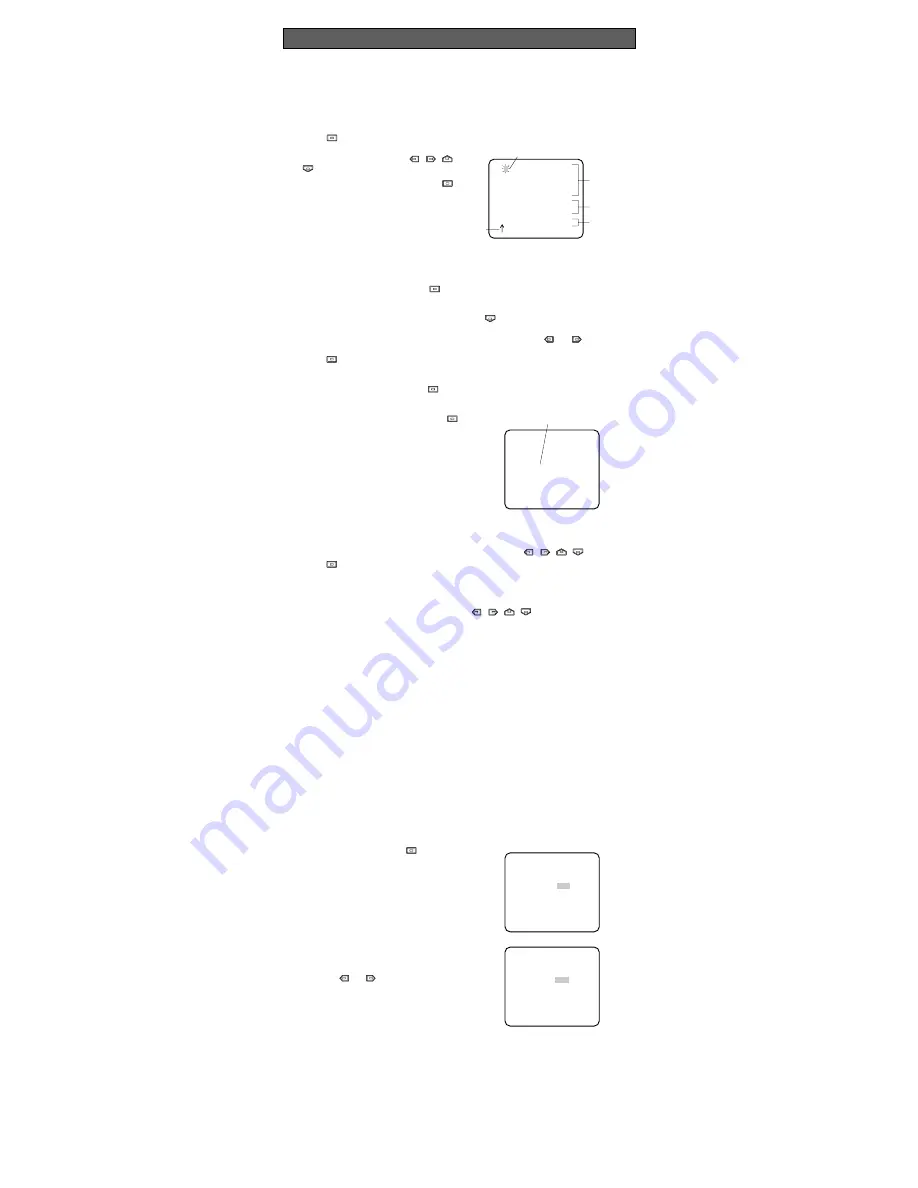
1. After selecting ALC, press 

to open

the ALC CONT menu.

2. Move the cursor to the SUPER-D2

parameter and select ON

3. If you want to adjust the video output

level, move the cursor to the "I" posi-
tion. Adjust to the desired level by
pressing or .

   ** ALC CONT **
   BACK LIGHT COMP

SUPER-D2     OFF

MASK SET   

LEVEL        ...I.....
             -       +

RET  END

   ** ALC CONT **
   BACK LIGHT COMP

SUPER-D2     ON

LEVEL        ...I.....
             -       +

RET  END

1. Camera Identification (CAMERA ID) Setting

You can use the camera identification (CAMERA ID) to assign a name to the camera.  The
camera ID consists of up to 16 alphanumeric characters.  The camera ID display can be
switched on or off on the monitor screen.

To edit the CAMERA ID

1. Move the cursor to the CAMERA ID parameter.

2. Press 

.  The CAMERA ID menu appears.  The cursor on the letter “0” is highlighted.

3. Move the cursor to the character you

want to edit by pressing 

/

/

/

.

4. After selecting the character, press 

.

The selected character appears in the
editing area.  (The pointer in the editing
area moves to the right automatically at
this moment.)

5. Repeat the steps above until all charac-

ters are edited.

To enter a blank space in the CAMERA ID

Move the cursor to SPACE and press 

.

To replace a specific character in the CAMERA ID

1. Move the cursor to the editing area by pressing 

.

2. Move the pointer to the character to be replaced by pressing 

or 

.  Then move

the cursor to the character area and select a new character.

3. Press 

to determine the CAMERA ID.

To erase all characters in the editing area

Move the cursor to RESET and press 

.  All characters in the editing area disappear.

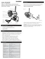
To determine the display position of the CAMERA ID

1. Move the cursor to POSI, and press 

.

The display shown below appears and
the CAMERA ID is highlighted.

WV-CP460

Highlighted

   0123456789
   ABCDEFGHIJKLM
   NOPQRSTUVWXYZ
   ().,'":;&#!?=
   +-*/%$

  SPACE
  POSI RET END RESET

  ................

Character Cursor

Pointer

Character
Area

Command

Editing
Area

CAMERA ID menu

SETTING PROCEDURES

Summary of Contents for WVCP460 - COLOR CCTV CAMERA

Page 1: ...itute a risk of electric shock to persons The serial number of this product may be found on the top of the unit You should note the serial number of this unit in the space provided and retain this instruction as a permanent record of your purchase to aid identification in the event of theft Model No Serial No SA 1966 SA 1965 N0100 1020 YWV8QA5377BN Printed in Japan N 19 Panasonic s WV CP460 WV CP4...

Page 2: ... 2 5 3 4 Super Dynamic WV CP460 Hi Z G L 75Ω VIDEO OUT 120V AC 60Hz GEN LOCK AC 24V IN DC 12V IN 1 2 VIDEO OUT GND GEN LOCK LOCK Slide the panel to the left until it locks CONNECTIONS A WV CP460 120 V AC 60 Hz 1 Plug the AC power cord supplied as standard accessory into the AC Inlet Socket 2 Connect the AC power cord to a 120V AC 60 Hz outlet Notes Connect the power cord firmly The power cord shou...

Page 3: ...s used to connect an external system for synchronization 3 Video Output Connector VIDEO OUT This connector is used to connect the VIDEO IN connector of the monitor 4 AC Inlet Socket This socket is used to connect the power cord supplied as a standard accessory 5 AC DC Compatible Input Terminal DC 12 V IN AC 24 V IN This terminal is for connecting the 12 V DC or 24 V AC power supply cord 6 High qua...

Page 4: ... 3 Tighten the screw on the side of the camera Caution Tightening the screw by force will cause damage to the screw or deviation of focus FOCUS OR FLANGE BACK ADJUSTMENT Mounting from the top Remove the mount adapter from the bottom of the camera by removing the two fixing screws Attach the mount adapter to the top as shown in the diagram then mount the camera on the mounting bracket Make sure tha...

Page 5: ...n the bottom line Press SET UP DISABLE changes to SET UP ENABLE Move the cursor to END then to the item s you want to change Important Notice When the cursor is moved to END and the CAM SET UP menu closed after changing the parameters the new values are saved in the EEPROM Electric Erasable and Programmable Read Only Memory These values remain valid until new values are saved even if the power of ...

Page 6: ...MASK SET LEVEL I RET END ALC CONT BACK LIGHT COMP SUPER D2 ON LEVEL I RET END 1 Camera Identification CAMERA ID Setting You can use the camera identification CAMERA ID to assign a name to the camera The camera ID consists of up to 16 alphanumeric characters The camera ID display can be switched on or off on the monitor screen To edit the CAMERA ID 1 Move the cursor to the CAMERA ID parameter 2 Pre...

Page 7: ...vel adjustment ON or fixed level OFF Note If ON is selected for the AGC parameter the noise reduction function is automatically activated under low light conditions to reduce noise In pictures containing a moving object this may result in an afterimage 5 Electronic Sensitivity Enhancement SENS UP There are two modes for SENS UP AUTO If you select X10 AUTO for example the sensitivity is raised auto...

Page 8: ...just the horizontal phase by pressing or The adjustable range is 0 2 0 µs 9 Move the cursor to SC COARSE 10 Press or to match the chroma phase of the camera s video signal when observed at the output of the special effects generator SEG or Switcher as closely as possible to the color of the original scene SC COARSE adjustment can be increment ed in steps of 90 degrees 4 steps by pressing or Note A...

Page 9: ...or white balance adjustment as follows ATW Auto Tracing White Balance In this mode the color temperature is monitored continuously and thereby white bal ance is set automatically The color temperature range for the proper white balance is approximately 2 600 6 000K Proper white balance may not be obtained under the fol lowing conditions 1 The color temperature is out of the 2 600 6 000K range 2 Wh...

Page 10: ...s Drive Signal Selection LENS DRIVE This item is used to select the type of auto iris lens drive signal to be supplied to the lens from the auto iris lens connector 1 Move the cursor to the LENS DRIVE parameter 2 Select DC if you are using the auto iris lens that requires a DC drive signal Select VIDEO if you are using the auto iris lens that requires a video drive signal 10 Special Menu This menu...

Page 11: ...4 8 W Power Consumption WV CP464 24 V AC 60 Hz 4 9 W 12 V DC 490 mA Dimensions without lens 74 W x 55 H x 123 D mm 2 15 16 W x 2 3 16 H x 4 13 16 D Weights without lens WV CP460 0 41 kg 0 9 lbs without power cord WV CP464 0 4 kg 0 9 lbs Weights and dimensions indicated are approximate Specifications are subject to change without notice SPECIFICATIONS OPTIONAL ACCESSORIES Lenses WV LA2R8C3B WV LA4R...

Reviews: