background image

Video Cable

1. It is recommended to use a monitor whose resolution is at least equal to that of the

camera.

2. The maximum extensible coaxial cable length between the camera and the monitor is

shown below.

Cautions:

1. Connect to 12 V DC (10.8 V-16 V) or 24 V AC (19.5 V-28 V) class 2 power supply

only.  Make sure to connect the grounding lead to the GND terminal when the power
is supplied from a 24 V AC power source.

2. To prevent fire or electric shock hazard, use a UL listed cable (VW-1, style 1007) for

the Input Terminal.

y

Down Button (

)

This button is used to move the cursor downward.  It is also used to select items in the
CAM SET UP menu.

u

Left Button (

)

This button is used to move the cursor to the left.  It also selects the mode and can be
used to adjust some levels.

i

Up Button (

)

This button is used to move the cursor upward.  It is also used to select items in the
CAM SET UP menu.

o

Right Button (

)

This button is used to move the cursor to the right.  It also selects the mode and can be
used to adjust some levels.

!0

Set Button (

)

This button is used to activate an item selected in the CAM SET UP menu.

!1

Gen-lock Termination Switch (Hi-Z, G/L 75 

)

Set this switch to Hi-Z when a gen-lock video input signal is looped through.  In all other
cases, set this switch to 75 

.

!2

Gen-lock Input Connector (GEN-LOCK)

This connector is used to connect an external system for synchronization.

!3

Video Output Connector (VIDEO OUT)

This connector is used to connect the VIDEO IN connector of the monitor.

!4

AC Inlet Socket

This socket is used to connect the power cord (supplied as a standard accessory).

!5

AC/DC Compatible Input Terminal
(DC 12 V IN/AC 24 V IN)

This terminal is for connecting the 12 V DC or 24 V AC power supply cord.

6. High quality picture:

(a) 2H type vertical enhancer for greater picture sharpness

(b) Chroma averaging circuit for better color signal-to-noise ratio

(c) Minimum of aliasing on fine objects

(d) Expanded dynamic range by use of knee circuit

(e) Highlight aperture correction for greater picture detail of bright objects

7. Ability to shoot indoor scenes with fixed iris lens by use of Electronic Light Control (ELC)

function.

8. Selectable electronic sensitivity enhancing modes including AUTO, MANUAL and OFF
9. Built in Digital Motion Detector

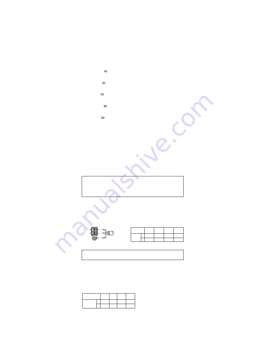
2. 24 V AC Power Supply

Connect the power cable to the AC/DC compatible input terminal on the rear panel of
the camera.

Copper wire

#24

#22

#20

#18

size (AWG)

(0.22mm

2

) (0.33mm

2

) (0.52mm

2

) (0.83mm

2

)

Length

(m)

95

150

255

425

of Cable
(Approx.) (ft)

314

495

842

1 403

Recommended wire gauge sizes for 24 V AC line.

AC  24V

IN

DC  12V

IN

1

2

GND

24 V AC, 60 Hz
(19.5 V - 28 V)

Caution:

To prevent fire or electric shock hazard, use a UL listed cable (VW-1, style 1007).

Type of

RG-59/U

RG-6U RG-11/U RG-15/U

coaxial cable

(3C-2V)

(5C-2V) (7C-2V)

(10C-2V)

Recommended (m)

250

500

600

800

maximum
cable length

(ft)

825

1 650

1 980

2 640

Summary of Contents for WVCP460 - COLOR CCTV CAMERA

Page 1: ...itute a risk of electric shock to persons The serial number of this product may be found on the top of the unit You should note the serial number of this unit in the space provided and retain this instruction as a permanent record of your purchase to aid identification in the event of theft Model No Serial No SA 1966 SA 1965 N0100 1020 YWV8QA5377BN Printed in Japan N 19 Panasonic s WV CP460 WV CP4...

Page 2: ... 2 5 3 4 Super Dynamic WV CP460 Hi Z G L 75Ω VIDEO OUT 120V AC 60Hz GEN LOCK AC 24V IN DC 12V IN 1 2 VIDEO OUT GND GEN LOCK LOCK Slide the panel to the left until it locks CONNECTIONS A WV CP460 120 V AC 60 Hz 1 Plug the AC power cord supplied as standard accessory into the AC Inlet Socket 2 Connect the AC power cord to a 120V AC 60 Hz outlet Notes Connect the power cord firmly The power cord shou...

Page 3: ...s used to connect an external system for synchronization 3 Video Output Connector VIDEO OUT This connector is used to connect the VIDEO IN connector of the monitor 4 AC Inlet Socket This socket is used to connect the power cord supplied as a standard accessory 5 AC DC Compatible Input Terminal DC 12 V IN AC 24 V IN This terminal is for connecting the 12 V DC or 24 V AC power supply cord 6 High qua...

Page 4: ... 3 Tighten the screw on the side of the camera Caution Tightening the screw by force will cause damage to the screw or deviation of focus FOCUS OR FLANGE BACK ADJUSTMENT Mounting from the top Remove the mount adapter from the bottom of the camera by removing the two fixing screws Attach the mount adapter to the top as shown in the diagram then mount the camera on the mounting bracket Make sure tha...

Page 5: ...n the bottom line Press SET UP DISABLE changes to SET UP ENABLE Move the cursor to END then to the item s you want to change Important Notice When the cursor is moved to END and the CAM SET UP menu closed after changing the parameters the new values are saved in the EEPROM Electric Erasable and Programmable Read Only Memory These values remain valid until new values are saved even if the power of ...

Page 6: ...MASK SET LEVEL I RET END ALC CONT BACK LIGHT COMP SUPER D2 ON LEVEL I RET END 1 Camera Identification CAMERA ID Setting You can use the camera identification CAMERA ID to assign a name to the camera The camera ID consists of up to 16 alphanumeric characters The camera ID display can be switched on or off on the monitor screen To edit the CAMERA ID 1 Move the cursor to the CAMERA ID parameter 2 Pre...

Page 7: ...vel adjustment ON or fixed level OFF Note If ON is selected for the AGC parameter the noise reduction function is automatically activated under low light conditions to reduce noise In pictures containing a moving object this may result in an afterimage 5 Electronic Sensitivity Enhancement SENS UP There are two modes for SENS UP AUTO If you select X10 AUTO for example the sensitivity is raised auto...

Page 8: ...just the horizontal phase by pressing or The adjustable range is 0 2 0 µs 9 Move the cursor to SC COARSE 10 Press or to match the chroma phase of the camera s video signal when observed at the output of the special effects generator SEG or Switcher as closely as possible to the color of the original scene SC COARSE adjustment can be increment ed in steps of 90 degrees 4 steps by pressing or Note A...

Page 9: ...or white balance adjustment as follows ATW Auto Tracing White Balance In this mode the color temperature is monitored continuously and thereby white bal ance is set automatically The color temperature range for the proper white balance is approximately 2 600 6 000K Proper white balance may not be obtained under the fol lowing conditions 1 The color temperature is out of the 2 600 6 000K range 2 Wh...

Page 10: ...s Drive Signal Selection LENS DRIVE This item is used to select the type of auto iris lens drive signal to be supplied to the lens from the auto iris lens connector 1 Move the cursor to the LENS DRIVE parameter 2 Select DC if you are using the auto iris lens that requires a DC drive signal Select VIDEO if you are using the auto iris lens that requires a video drive signal 10 Special Menu This menu...

Page 11: ...4 8 W Power Consumption WV CP464 24 V AC 60 Hz 4 9 W 12 V DC 490 mA Dimensions without lens 74 W x 55 H x 123 D mm 2 15 16 W x 2 3 16 H x 4 13 16 D Weights without lens WV CP460 0 41 kg 0 9 lbs without power cord WV CP464 0 4 kg 0 9 lbs Weights and dimensions indicated are approximate Specifications are subject to change without notice SPECIFICATIONS OPTIONAL ACCESSORIES Lenses WV LA2R8C3B WV LA4R...

Reviews: