background image

52

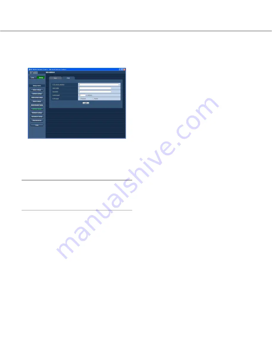
Configure the settings relating to the FTP server [FTP]

Click the [FTP] tab on the "Server setup" page. (

pages 4 and 5: How to display/operate the setup menu)

The settings relating to the FTP server used to transmit the alarm images can be configured on this page. 

[FTP server address]

Enter the IP address or the host name of the FTP serv-
er. 

Number of characters for the FTP server address:

1 - 128 characters

Important:

When entering the host name for "FTP server
address", it is necessary to configure the DNS set-
tings on the [Network] tab of the "Network setup"
page. (

page 54)

[User name]

Enter the user name (login name) to access the FTP
server. 

Number of characters for the user name:

1 - 32 char-

acters

[Password]

Enter the password to access the FTP server. 

Number of characters for the password:

0 - 32 char-

acters

[Control port]

Enter a control port number to be used for the FTP serv-
er.

Available port number:

1 - 65535

Default:

21

[FTP mode]

Select "Passive" or "Active" for the FTP mode.
Normally, select "Passive". When failure to establish the
connection occurs, select "Active".

Default:

Passive

Summary of Contents for WV-NS950 series

Page 1: ...onnect or operate this product please read these instructions carefully and save this manual for future use Network Camera Setup Instructions Model Nos WV NS950 WV NS954 WV NW960 WV NW964 WV NS950 WV NS954 WV NW960 WV NW964 ...

Page 2: ...figures the multi screen settings Multi screen setup 37 Configure the alarm settings Alarm setup 38 Set the VMD areas VMD area 43 Configure the settings relating to the authentication Authentication setup 49 Configure the settings of the servers Server setup 51 Configuring the network settings Network setup 53 Configure the settings relating to the schedules Schedule setup 61 Maintenance of the ca...

Page 3: ... or trademarks of Adobe Systems Incorporated in the United States and or other countries SD logo is a trademark Mini SD is a trademark Other names of companies and product contained in these operating instructions may be trademarks or regis tered trademarks of their respective owners Viewer software Images will not be displayed when the viewer software Network camera View3 is not installed on the ...

Page 4: ...s 1 Administrator How to display the setup menu Step 1 Display the Live page Operating instructions Step 2 Click the Setup button on the Live page The window with the user name and password entry fields will be displayed Step 3 Click the OK button after entering the user name and the password The setup menu will be displayed Refer to the next page for further information about this menu ...

Page 5: ...the window Step 3 After completing each setting item click the SET but ton to apply them Important When there are two or more SET buttons on the page click the respective button to the edited setting item Example When completing the setting items in field A click the SET button below field A A 1 The edited set ting items in field A will not be applied unless the SET button below field A A 1 is cli...

Page 6: ... Alarm setup page The settings relating to alarm occurrences such as settings for the alarm action at an alarm occurrence the alarm occurrence notification and the VMD area settings can be configured on the Alarm setup page Refer to page 38 for further information y Authentication setup button Click this button to display the Authentication setup page The settings relating to the authentication su...

Page 7: ...m input or to allow to activate the video motion detection VMD func tion Refer to page 61 for further information 0 Maintenance button Click this button to display the Maintenance page System log check firmware upgrade and initializa tion of the setup menu can be carried out on the Maintenance page Refer to page 62 for further information 1 Help button Click this button to display the Help page 2 ...

Page 8: ...urrent hour reflecting this setting when entering the current time and date for Time date setup To hide time and date select OFF Default 24 hours Date time display format Select a date time display format When 07 04 01 13 10 00 is set for Time date setup after selecting 24 hours for Time display time and date will be respectively displayed as follows DD MM YYYY 01 04 2007 13 10 00 MM DD YYYY 04 01...

Page 9: ...ceiver button the transmission button the AUX button or the SD saving status indication button will be displayed to notify of the camera status Polling 30 sec Updates the status each 30 seconds and provide notification of the camera status Real time Provide notification of the camera status when the status has changed Default Real time Note Depending on the network environment notification may not...

Page 10: ...nchronizing with the NTP server will be used as the standard time of the camera Default Manual setup NTP server address Enter the IP address or the host name of the NTP serv er Number of characters for the NTP server address 1 128 characters Default None blank Important When entering the host name for NTP server address it is necessary to configure the DNS set tings on the Network tab of the Netwo...

Page 11: ...d the values above For example notification will be provided each time the remaining space reaches 50 20 10 5 and 2 when 50 is selected Notification may not always be made at the very moment when the remaining space of the SD memory card has reached each value Save trigger Select a trigger to save images on the SD memory card from the following FTP error Saves images when images have failed to tra...

Page 12: ...ges to be saved on the SD memory card Default VGA Notes When FTP error is selected for Save trigger images will be saved with the image capture size selected on the FTP tab of the Network setup page When Alarm input is selected for Save trigger images will be saved with the image capture size selected on the Alarm tab of the Alarm setup page SD memory card information SD memory card Available size...

Page 13: ...r ing the process of formatting All data saved on the SD memory card will be delet ed when the SD memory card is formatted Do not turn off the power of the camera during the process of formatting After formatting the SD memory card the available size may be smaller than the total size since the default directory is automatically created in the SD memory card Compatible SD memory card is as follows...

Page 14: ... be obtained via a network In this case refer to the network administrator Step 1 Click the Execute button of Access images The user authentication window will be displayed Step 2 Click the OK button after entering the user name and the password The folder in which images are to be saved will be displayed Step 3 Copy the desired images or the folder onto the PC It is impossible to display the imag...

Page 15: ...ox 4 000 pics Approx 2 000 pics Approx 1 000 pics 2 GB 1 GB 512 MB 256 MB 128 MB 64 MB Approx 24 000 pics Approx 12 000 pics Approx 6 000 pics Approx 3 000 pics Approx 1 500 pics Approx 750 pics Approx 26 000 pics Approx 13 000 pics Approx 6 500 pics Approx 3 250 pics Approx 1 625 pics Approx 812 pics Approx 27 000 pics Approx 13 500 pics Approx 6 750 pics Approx 3 375 pics Approx 1 687 pics Appro...

Page 16: ...ch images associated with the logs are to be downloaded For example enter C alarm to designate the folder alarm under drive C Enter 3 to 128 characters Enter alphanumeric characters except the following _ Manual Select ON or OFF and designate the destination folder in the same manner as for Alarm FTP error Select ON or OFF and designate the destination folder in the same manner as for Alarm Import...

Page 17: ...ages when more than 5 000 logs are filed since associated images are to be deleted when the logs are deleted Logs Up to 1 000 logs will be kept When more than 1 000 logs are filed the older logs will be overwritten by the newer logs In this case the oldest log is the first to be overwrit ten When the power of the camera is turned off logs will be deleted Images Images will not be saved Note To dis...

Page 18: ...aved Images Images will not be saved Logs Logs will not be saved Images Images will be saved When available capacity of the SD memory card ran out the older images will be overwritten by the newer images In this case the oldest image is the first to be over written Note To display images on the SD memory card it is neces sary to copy them onto the PC first page 14 Logs Logs will not be saved Image...

Page 19: ...How the logs and images are saved depending on the settings for FTP error LOG tab ON FTP error Save logs SD memory card tab SD memory card Use Save trigger FTP error Logs Up to 5 000 logs will be kept When more than 5 000 logs are filed no log will be filed newly anymore Even when available capacity of the SD memory card ran out and it is not enough to save images logs will be kept on being filed ...

Page 20: ... such as Refresh interval JPEG Image capture size and Image quality on this section Refer to page 21 for further information about the settings relating to MPEG 4 images Refresh interval JPEG Select an interval to refresh the displayed JPEG image from the following 0 1 fps 0 2 fps 0 33 fps 0 5 fps 1 fps 2 fps 3 fps 5 fps 6 fps 10 fps 15 fps 30 fps Default 5 fps Note When ON is selected for MPEG 4 ...

Page 21: ...imited Default 2048 kbps Note The MPEG 4 bit rate is synchronized with Total bit rate on the Network tab of Network setup page page 54 For this reason the bit rate may be lower than the value when any value with an asterisk on the right is selected Image capture size Select QVGA or VGA for the image capture size of MPEG 4 images Default VGA Image quality Select the image quality of MPEG 4 images f...

Page 22: ...ast port2 Audio Enter the unicast port number used to transmit audio from the camera Available port number 1024 50000 Only even num bers are available Default 33004 Multicast address Enter the multicast IP address Images and audio will be transmitted to the designated IP address Available IP address 224 0 0 0 239 255 255 255 Default 239 192 0 20 Multicast port Enter the multicast port number used ...

Page 23: ...ra is turned on OFF The camera will not be in any mode Home position When the set time has passed the camera will move to the home position automatical ly Auto track When the set time has passed the camera will move to the home position and will start the auto track function The camera will repeat this action moves to the home position and starts the auto track function afterward Auto pan When the...

Page 24: ...OFF Notes When ON is selected zooming will stop when the zoom factor has reached 30x When the zoom factor is increased to 30x EL zoom or more the image resolution will be lower When the zoom factor is 30x or more the setting of the preset positions will become unavailable Pan Tilt degree Zoom ratio display Select ON or OFF to determine whether or not to dis play the current panning tilting degree ...

Page 25: ...elating to image quality The setup menu will be displayed in a newly opened window page 26 Preset Position Click the SETUP button to display the setup menu that can configure the settings relating to the preset positions The setup menu will be displayed in a newly opened window page 30 Auto Pan Click the SETUP button to display the setup menu that can configure the settings relating to the auto pa...

Page 26: ...g cases turn off SUPER D 3 When flickering appears or the colour changes on the screen When noise appears in the brighter area on the screen About SUPER D 3 Super Dynamic function When there is wide variation between the illumination of light and dark areas of the location being monitored the camera adjusts the lens iris in accordance with the brighter areas This causes loss of detail in darker ar...

Page 27: ...trol mode Suitable for shooting where the light source is fixed and the light intensity is constant Operating colour temperature range is approx 2 000 K 10 000 K Default ATW1 Mask area When OFF is selected for Super Dynamic 3 it is possible to compensate for backlight by masking the brighter area Refer to page 29 for descriptions of how to mask Shutter Select the shutter speed from the following A...

Page 28: ...Reduction When this function digital noise reduction is active noise may be automatically reduced under a low lumi nance Select an effect level LOW or HIGH for the digital noise reduction HIGH High DNR afterimage remains LOW Low DNR reduces afterimage Default HIGH Chroma gain level Adjust the chroma level colour density When the cursor is moved in the direction the colours will become thicker When...

Page 29: ...ear and the image displayed on the Image Position tab will be divided into 48 6x8 Step 3 Click the divided areas to be masked The clicked areas will be masked and will become white To cancel masking click the area again Step 4 Click the END button after completing masking areas The borders on the image displayed on the Image Position tab will disappear Note When the RESET button is clicked masking...

Page 30: ...Position No Step 3 To display the preset ID on the Live page select ON for Preset ID and enter the desired preset ID to be dis played Then click the SET button to apply the set tings Step 4 The settings of Auto focus Dwell time Super Dynamic 3 and Mask area can be configured for each position independently Notes When the displayed image is being zoomed in more than x30 it is impossible to register...

Page 31: ...e preset ID to be displayed on images The pre set IDs can be applied to each preset position Available characters 0 9 A Z and the following marks Number of characters for the preset ID 0 16 char acters Default None blank Note The entered preset ID will be displayed next to the preset position number on the pull down menu When ON is selected for Preset ID the preset ID will be displayed on images A...

Page 32: ...d posi tion Auto pan Dwell time Select a dwell time at the left position and the right posi tion from the following 5 sec 10 sec 20 sec 30 sec Default 5 sec Speed Select a speed for the auto panning from the following 3 sec 4 sec 5 sec 7 sec 10 sec 13 sec 18 sec 24 sec Default 13 sec Note Even when the selected zoom factor is higher than 30x the camera will start panning with 30x zoom factor Impor...

Page 33: ...licking the Confirm button with the patrol number selected demonstrates the stored camera operation Note Storable camera operations are described below q At starting operation Pan position tilt position zoom position focus position brightness setting super dynamic 3 set ting shutter speed setting gain setting electron ic sensitivity enhancing white balance setting R volume setting and B volume set...

Page 34: ...or the number A blinking mask will be displayed at the center of the image displayed on the Image Position tab Operate the camera with the panning tilting zooming operations to cover the area to be covered by the blink ing mask This setting is performed after operating the camera with the panning tilting zooming operations to determine the size and position for mask matching with hidden areas To d...

Page 35: ... on this page Audio mode Select the communication mode used for audio data transmission reception between the camera and the PC from the following OFF Does not receive transmit audio between the cam era and the PC Therefore the settings and controls relating to audio will be invalidated Mic input The PC receives audio data from the cam era Audio can be heard with images on the PC Images and audio ...

Page 36: ...d even though the delay time will be longer Select the interval according to the network environ ment Audio may temporarily be interrupted or noise may be heard when panning tilting or zooming the cam era or when multiple users are accessing concur rently It may be possible to diminish the interruption or noise by setting a longer interval for Audio output interval PC to Camera Audio output port P...

Page 37: ...camera to be used for the multi screen 4 cameras can be regis tered as a group and up to 4 groups 16 cameras can be registered When the HTTP port number for the camera had been changed enter as follows IP address of the camera port number for example 192 168 0 10 8080 Number of characters for the IP address 1 128 characters Note When using the host name it is necessary to config ure the DNS settin...

Page 38: ...cordance with input Note When an input is provided to the Black white input during patrol the patrol action stops If the patrol action is continued select Patrol 1 in the Self return box Default OFF Terminal alarm 2 Determine whether or not to use a terminal alarm 2 by selecting OFF Alarm input or Alarm output OFF Does not use alarms Alarm input Uses alarms Alarm output Alarm output will be carrie...

Page 39: ...terminal alarm 1 is detected the camera will start the auto tracking When the home position is set the camera will start auto tracking after moving to the home position once Patrol 1 When a terminal alarm 1 is detected the cam era will start the patrol 1 operation Default OFF Terminal alarm 2 Select an action to be taken when a terminal alarm 2 is detected from the following OFF Does not take any ...

Page 40: ...PEN and CLOSE from the Live page It is useful when controlling the connected external device For example when it is necessary to control lighting at the camera location connect a lighting control device to the terminal AUX OUT of the camera to remotely control lighting at the camera location VMD alarm Select an action to be taken when a VMD alarm is detected from the following OFF Does not take an...

Page 41: ...y hour minute second Serial number Number of characters for the file name 1 32 char acters Post alarm Transmission interval Select the transmission interval for the alarm image transmission to the FTP server from the following 0 1 fps 0 2 fps 0 33 fps 0 5 fps 1 fps Default 1 fps Number of images Select the number of images to be transmitted from the following 1 pic 2 pics 3 pics 4 pics 5 pics 6 pi...

Page 42: ...is clicked Pulse When an alarm is detected the alarm output ter minal will be in the state to the Alarm output setting for the period set for Pulse width Default Latch Alarm output Select Open or Close to determine whether to open or close the alarm output terminal when outputting the alarm signals OPEN The alarm output terminal will open when out putting the alarm signals Normally close CLOSE The...

Page 43: ... for the VMD areas It is possible to display the alarm occurrence indication button on the VMD area tab when motion is detected by the VMD function Operating Instructions Select ON for VMD alarm on the Alarm tab when the alarm occurrence indication button is to be displayed The alarm occurrence indication button will be displayed when receiving a terminal alarm or a command alarm Depending on the ...

Page 44: ...areas except areas used for the time and date display of OSD position will be subject to the detection The VMD area setting is unavailable Status Select ON or OFF to determine whether or not to carry out the VMD function ON Carries out the VMD function OFF Does not carry out the VMD function Default OFF Detection sensitivity Select a sensitivity level in the detection area from the following 1 Sup...

Page 45: ... will be displayed When 2 4 VMD areas are set each area will be numbered in order The areas will be identified by the respective outline colours When the VMD area is created Status of the created VMD area will be set to ON automati cally Step 4 Select ON or OFF for Status of each VMD area When the SET button is clicked after selecting OFF the outline will become a broken line and no alarm action w...

Page 46: ... will not be applied unless the SET but ton is clicked Delete the VMD area set for the designated preset position Step 1 Display the VMD area setup window of the preset posi tion number whose VMD area is to be deleted page 45 Step 2 Click the Delete button respective to the area to be deleted The outline of the area will disappear Step 3 Click the SET button The deletion will be completed Importan...

Page 47: ...ddress Enter the destination mail address Up to 4 destination addresses can be registered To provide notification by e mail when an alarm has occurred check the Alarm checkbox respective to the desired address To provide notification by e mail when any of the follow ing has occurred check the Diag checkbox respective to the desired address When notification of the remaining space of the SD memory ...

Page 48: ...alarm protocol Available retry times 0 30 Default 2 Panasonic alarm protocol Destination IP address Enter the destination IP address of the Panasonic alarm protocol from the following Host name is unavailable for the destination IP address Up to 8 destination address es can be registered To provide notification at an alarm occurrence to the desired IP address using Panasonic alarm protocol check t...

Page 49: ...me 1 32 char acters Default None blank Password Retype password Enter the password Number of characters for the password 4 32 char acters Default None blank Note When the user name already in use is entered and the SET button is clicked the respective user infor mation will be overwritten Access level Select the access level of the user from the following 1 Administrator Allowed all available oper...

Page 50: ...ailable for the IP address Notes When IP address subnet mask is entered it is pos sible to restrict PCs in each subnet For example when 192 168 0 1 24 is entered and 2 Camera control is selected for the access level the PCs whose IP address is between 192 168 0 0 192 168 0 255 can access the camera with the access level 2 Camera control When the IP address already in use is entered and the SET but...

Page 51: ...rver address 1 128 characters Important When entering the host name for SMTP server address POP server address it is necessary to configure the DNS settings on the Network tab of the Network setup page page 54 Authentication Select the authentication method to send e mails from the following None It is not necessary to clear any authentication to send e mails POP before SMTP It is necessary to fir...

Page 52: ...host name for FTP server address it is necessary to configure the DNS set tings on the Network tab of the Network setup page page 54 User name Enter the user name login name to access the FTP server Number of characters for the user name 1 32 char acters Password Enter the password to access the FTP server Number of characters for the password 0 32 char acters Control port Enter a control port num...

Page 53: ...p DHCP Select ON or OFF to determine whether or not to use the DHCP function Configure the DHCP server not to assign the same IP addresses used for the other network cameras and PCs whose IP address is unique Refer to the network administrator for further information about the settings of the server Default OFF IP address When not using the DHCP function enter the IP address of the camera Do not e...

Page 54: ...s Default MANUAL Primary DNS Secondary DNS When MANUAL is selected for DNS enter the IP address of the DNS Refer to the network administrator about the IP address of the DNS Line speed Select the line speed for data transmission from the fol lowing It is recommended to use the default setting AUTO AUTO Line speed will be applied automatically 100M FULL 100 Mbps full duplex 100M HALF 100 Mbps half ...

Page 55: ...ding function For further infor mation refer to the operating instructions of the router in use Enter Global IP address colon port number in the Address box of the browser via the Internet WAN Global address vvv xxx yyy zzz LAN Private address 192 168 0 254 vvv xxx yyy zzz 82 vvv xxx yyy zzz 81 Router Internet WAN Cable modem xDSL modem Address translation using the port forwarding function vvv xx...

Page 56: ...s 24 hours Default 1 hour Configure the settings relating to DDNS DDNS Click the DDNS tab on the Network setup page pages 4 and 5 How to display operate the setup menu The settings relating to DDNS can be configured on this page When accessing the camera via the Internet from the network environment of which the global IP address is obtained using DHCP the DDNS function is necessary When using the...

Page 57: ...ult None blank Important When using the SNMP function it is necessary to enter the community name When no community name is entered the SNMP function will not work Camera title Enter a camera title to be used to manage the camera with the SNMP function Number of characters for the camera title 0 32 characters Default None blank Camera location Enter the name of the location where the camera is ins...

Page 58: ... occur frequently Note When FTP error is selected for Save trigger on the SD memory card tab images that have failed to transmit using the FTP periodic transmission can be saved automatically on the SD memory card page 11 To FTP setup When To FTP setup is clicked the FTP tab of the Server setup page will be displayed page 52 FTP periodic transmission Select ON or OFF to determine whether or not to...

Page 59: ...alidated for the schedule Step 2 To designate time click i and select the desired hour and minute When not designating time check the checkbox of 24 hours Step 3 Click the SET button after completing the settings The result will be displayed at the bottom of the win dow Interval Select the interval for the FTP periodic transmission from the following 1 sec 2 sec 3 sec 4 sec 5 sec 6 sec 10 sec 15 s...

Page 60: ... How to delete the set schedule Step 1 Uncheck the check box of the set day of the week Step 2 Click the SET button after completing the settings The result will be displayed at the bottom of the win dow ...

Page 61: ...es Step 1 Select an action to be assigned to the schedule from MODE OFF No action will be taken for the respective sched ule Alarm permission Alarm input terminal alarm 1 2 and 3 will be received during the period of the schedule VMD permission The Video motion detection VMD function will be active during the period of the sched ule Access permission Users whose access level is set to 2 and 3 on t...

Page 62: ...he first to be overwritten The system logs will be displayed in group of 100 logs each When using the SD memory card the logs will be saved even when the power of the camera is turned off When not using the SD memory card the logs will be deleted when the power of the camera is turned off Time date Time and date at the error occurrence will be displayed Note When OFF is selected for Time display o...

Page 63: ...4 Click the Upgrade button The confirmation window will be displayed When Do not default settings after completing the upgrade is selected the confirmation window will not be displayed After completing the upgrade delete temporary inter net files page 74 Important Upgrade the firmware using a PC in the same sub net as the camera Follow the instructions from the dealer when upgrad ing the firmware ...

Page 64: ...amera and the HTML files to the default Note that the network settings and the preset position setting will not be reset Restart Click the Execute button to restart the camera Position refresh The camera position can be refreshed When the cam era has moved from the correct home preset position during normal use use this function to correct the cam era position Notes Please wait for approx 2 minute...

Page 65: ...en Step 1 Click the Setup button The setup screen is displayed Clicking an underlined item win display the Help pop window If is possible to configure the settings while displaying the Help pop up window Step 2 Click the Help button The Help screen is displayed Step 3 Click the desired item to display a detailed explanation for the corresponding operation 65 ...

Page 66: ...correctly The DNS server may be down Ask the network administrator The IP address of the server may be incorrect Check if the IP address of the server is configured correctly The SMTP server may be down Ask the network administrator Indication Description Category FTP server error Connection error Internal error Failed to resolve FTP server address from DNS Failed to find FTP server Transmission e...

Page 67: ...tor The login user name will be displayed when ON is selected for User authenti cation The IP address of the PC currently accessing to the camera will be displayed when ON is selected for Host authenti cation Time correction succeeded The designated IP address of the DNS may be incorrect Check if the DNS set tings are configured correctly The DNS server may be down Ask the network administrator En...

Page 68: ...e link LED beside the SD card slot for NS950 series or in the main unit for NW960 series lit When it is not lit connection to a LAN may not be established or a network may be not working correct ly Check if the cables have any contact failure or if the wiring is correct or not Is the power of the camera on Check if the power of the camera is turned on Installation Guide Troubleshooting Before aski...

Page 69: ...from the browser Images are displayed blurry 54 3 9 Installation Guide Is the entered password correct Restart the web browser and enter the password again Access to the SD memory card may be failed Restart the browser and retry to obtain images 14 14 Is the same IP address provided to other devices Are there contradictions between the address and the network subnet to be accessed When the camera ...

Page 70: ...your browser there might be difficulties refreshing the picture and operat ing the camera The slip ring may be dirty Perform position refresh Assign the position refresh function to a schedule and it is also recommended to clean the slip ring of the camera periodically When defocusing is caused by the camera position being moved carry out the position refresh to correct the focus This is not malfu...

Page 71: ... the SD memory card formatted Isn t the write protect switch set to LOCK When the write protect switch is set to LOCK avail able size total size indication of the SD memory card will be KB KB Installation Guide 12 Images cannot be saved on the SD memory card Is the brightness setting set at an appropriate level Click the RESET button of BRIGHTNESS Images are displayed washed out Operating Instruct...

Page 72: ...e viewer software Network Camera View3 is installed 3 9 Installation Guide Delete temporary internet files as follows 1 Select Internet Options from Tools on the menu bar of Internet Explorer The Internet Options window will be displayed 2 Click the Delete Files button in the Temporary Internet files section on the General tab The firewall function of the anti virus software may be filtering the p...

Page 73: ...nu 2 Select Settings from Display Properties and then click the Advanced button 3 Click the Troubleshoot tab and disable the DirectDraw acceleration by adjusting the level of Hardware acceleration When the DirectDraw acceleration is disabled by adjusting the level of Hardware acceleration no frame border will be displayed to indicate the selected area When displaying MPEG 4 images on two or more b...

Page 74: ...h Windows XP Service Pack2 SP2 is installed The following may occur during operation when using a PC on which Windows XP Service Pack2 SP2 is installed Follow the instructions below when the following has occurred By performing the following solutions other applica tions and the security level may not be affected The Information Bar expressed in the following symptom and solutions will be displaye...

Page 75: ...estination where images are to be saved by the SD memory recording function of Panasonic network disk recorder Destination where log files are to be saved Image failed to transmit to the FTP server by the FTP periodic tranmission function Ex img_07010101230000 jpg Image captured at the alarm occurrence Ex img_0701010123000001 jpg Image saved manually Ex img_0701010123000001 jpg ...

Page 76: ...01 Internet Step 3 Configure the router w to which the PC is connected as follows Address mapping table The address mapping table is the example for when using a typical router Depending on the manufacturer of the router it may be described as static IP masquerade Group Camera LAN IP address 192 168 0 10 192 168 0 10 192 168 0 10 LAN port TCP port 80 UDP port 32004 UDP port 33004 WAN IP address WA...

Page 77: ...asonic net Importer s name and address to follow EU rules Panasonic Testing Centre Panasonic Services Europe GmbH Winsbergring 15 22525 Hamburg F R Germany 2007 Matsushita Electric Industrial Co Ltd All Rights Reserved N1007 1127 3TR005325BAB Printed in Japan ...

Reviews: