


4. Input an area title.
The text input procedure is the same as that for
camera ID input.
See steps 3 through 5 under “Camera ID Settings”
on page 24 for information about inputting the text
for the area title and specifying its position on the
display.
5. Repeat steps 1 through 4 for the other area
numbers, if you want.
(13) Tilt Angle Setting (TILT ANGLE)
Selecting 5° for the TILT ANGLE setting allows tilting
past horizontal, in the range of -5° to 185°.
1. Move the cursor to TILT ANGLE, and then tilt the
joystick left or right to toggle the setting between 0°
and 5°.
Notes:
• Zooming to WIDE while 5° is selected for the
TILT angle setting will cause the upper half of
the picture to become hidden.
• With certain subjects, AGC (gain control) can
cause the image to become white.
(14) Cleaning Settings (CLEANING)
This camera uses a "slip ring" for transmission of
electrical power and signals. A dirty slip ring can cause
deterioration of picture quality and generation of noise.
The cleaning function performs cleaning approximately
once a week to keep the slip ring clean.
1. Move the cursor to CLEANING, and then tilt the
joystick left or right to toggle it on and off.
The text CLEANING appears in the centre of the
screen while the cleaning process is being
performed.
Note:
Select OFF for CLEANING when the system
controller uploads or downloads the preset data.
This protects against the download or upload failure
due to start up of the cleaning process.
6. Use the joystick to select an area title display
position, and then press the MON (ESC) button.
This registers the area title display position and
returns to the area title (NESW) setting menu.
Note:
The area title is always displayed under the
camera ID. If you specify different display position
settings for the camera ID and the area title ID, the
area title ID display position setting is used for both.
(2) When ON (USER) is selected
After selecting ON (USER), you can use the area title
(USER) setting menu to configure detailed settings.
You can use the following procedure to configure
direction settings, and to input text associated with a
particular direction indicator.
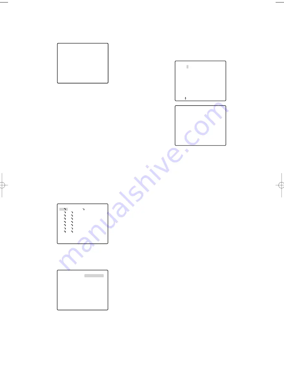
1. Move the cursor to 1, and then press the CAM
(SET) button.
This will display the position setting menu. An asterisk
(*) to the right of an area title number indicates that it
already has an area title assigned to it.
If the there is already text associated with the
direction you selected, it will appear under the
cross mark (+). If there is no text associated with
the direction, only the cross mark (+) will be
displayed.
2. Adjust the camera orientation (pan and tilt), zoom,
and focus.
Perform steps 1 through 4 under “(1) When ON
(NESW) is selected” on page 39.
3. Move the joystick to the right to align the cursor with
the title display, and press the CAM (SET) button.
This will display the area title setting menu.
In the example screen shown in step 1, NORTH
O
is the title name of area title number 1.
-40-
FLOOR 1
N
**AREA TITLE(USER)**
NORTH
2
3
4
5
6
7
8
RET TOP RESET
1*
AREA TITLE 1
123456789
ABCDEFGHIJKLM
NOPQRSTUVWXYZ
().,'":;&#!?=
+-*/%$
SPACE
---- POSI RET RESET
................
0
→
PUSH SET
**DIRECTION(USER) 1**
PAN/TILT
ZOOM/FOCUS
+
NORTH
RET TOP DEL
→
PUSH SET
FLOOR 1
NORTH
WV-CW970 974̲ENG.qxd 07.2.1 11:31 AM ページ40
Summary of Contents for WV-CW970
Page 2: ......
Page 62: ...62...
Page 186: ...186...
Page 311: ...311 3 CAUTION RISK OF ELECTRIC SHOCK DO NOT OPEN RUSSIAN VERSION...
Page 312: ...312 1 2 3 4 5 6 7 8 9 10 11 12 13 S3125A...
Page 313: ...313 1 2 3 4 5 6...
Page 315: ...315 WV Q122 353 340 10 354 355 354 355 354 355 1 5 316 1 2...
Page 317: ...317 348 350 359 RS485 331 362 WV CW974 WV CW864 WV CW864A 30 Panasonic CCTV 352 360...
Page 318: ...318 WV Q122 40 C o 50 C 240 1 RS485 DIP 322 DIP DIP 316 10 C 40 C...
Page 319: ...319 1 2 3 ZOOM...
Page 321: ...321 352 WV CW970 WV CW974 WARNING INPORTANT...
Page 325: ...325 WV Q122 1 1 2 3 2 1 3 M6 58 60 25 85 40 1 1 2A 30 MAX PT11 40 1 1 2B 30 MAX PT11 x3...
Page 326: ...326 2 4 M6 3 1 2 3 4 4 2 2 REAR 5 0 51 4 1 START 2 4 START x4...
Page 327: ...327 3 3 1 2 3 5 0 51 1 1 2 3 3...
Page 328: ...328 4 START LOCK 5 5 0 51...
Page 330: ...330 A 3 y 3 MOLEX 57027 5000 UL Style Cable UL1015 57026 5000 UL Style UL1007 24 2...
Page 352: ...352 AGC 14 1...
Page 354: ...354 5 1 6 1 7 1 8 1 5 1 356 CNT CLS1 9 1 O 10C 20C 30C 40C 50C 1 2 3 5 10 1C 10C 30C 1 3 5...
Page 355: ...355 2 3 10 349 3 10 1 SET SET I 128 1 8 ZOOM MODE TOP 20 55 351...
Page 361: ...361 1 335 O CAM SET 336 H TOP...
Page 366: ...366 339 340 340 340 339 340 317 343 352 318 343 SENS UP...
Page 367: ...367 318 359 360 341 339 340 342 342 342 359 322 324 329 331 Super Dynamic 3 DNR PIX OFF 317...
Page 368: ...368 362 358 347 346 357 358 356 357 A IN 4 A IN...
Page 369: ...369 346 360 336 337 351 352 317 318 353 354 354 353 353...
Page 370: ...370 353 43 353 343 353 353 353...
Page 373: ......
Page 374: ......


