


Camera settings
■
Using the Camera Setup Menu
Display the camera setup menu from the setup
menu (Advanced Menu) to configure camera
settings (page 27).
1. Display the setup menu (page 24), move the cursor to
CAMERA
O
, and then press the CAM (SET) button.
This will display the camera setup menu.
* The following sections numbered
q
to
!3
explain
how to use each of the camera setup menu items.
(1) Camera ID (CAMERA ID)
See page 24 for information on the camera ID
settings method. The factory default setting is OFF.
(2) Light Control (ALC/MANUAL)
1. Move the cursor to ALC/MANUAL, and then tilt the
joystick left or right to toggle between ALC and
MANUAL.
ALC
:
Enables automatic lens iris adjustment in
accordance with subject brightness.
Select this ALC when using SUPER-D
3
.
This is the factory default setting.
MANUAL:
Adjust the lens iris with the IRIS button on
the system controller. Fixes the lens iris.
Note:
The backlight compensation submenu
associated with this menu is described separately
and should be set up after installing the camera at
the site and observing the actual site picture.
2. If ALC is set in step 1, press the CAM (SET) button
to set SUPER-D
3
.
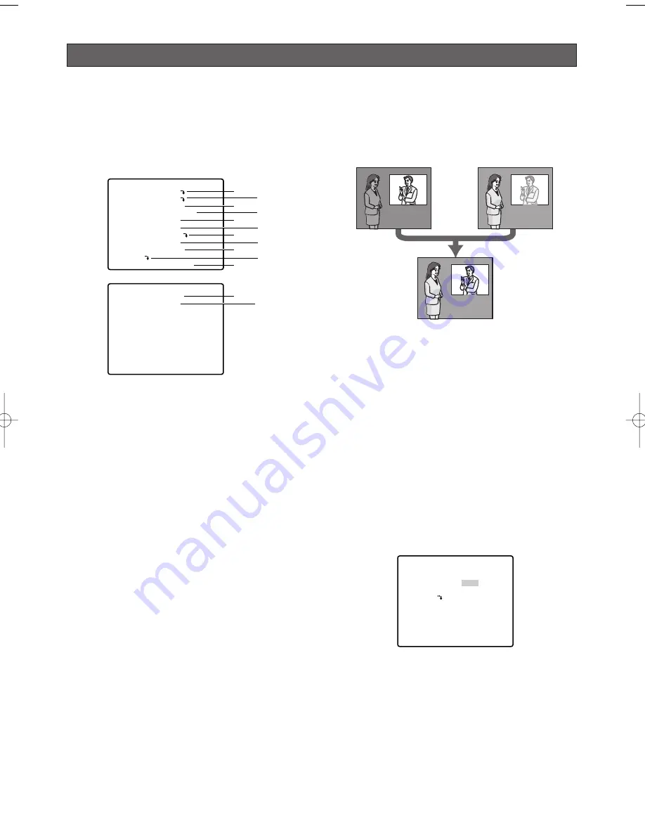
SUPER-D
3
3
(Super Dynamic
3
3
)
When there is wide variation between the illumination of
light and dark areas of the location being monitored,
the camera adjusts the lens iris in accordance with the
bright areas. This causes loss of detail in dark areas.
Conversely, adjusting lens brightness for the dark
areas cause brighter area to become washed out.
SUPER-D
3
digitally combines an image that is set up
for a clear view of bright areas with an image that is set
up for a clear view of dark areas, creating a final image
that preserves overall detail.
Notes:
• SUPER-D
3
is supported only when ALC is
selected for light control (ALC/MANUAL).
• Camera settings are limited to the following when
SUPER-D
3
is turned on.
SHUTTER :
OFF, AUTO (page 29)
SENS UP :
OFF, AUTO (page 29)
• If lighting conditions cause either of the following
phenomena, turn off SUPER-D
3
.
(1) Screen flickering or abnormal colour
(2) Digital noise in the bright areas of the screen
3. Move the cursor to SUPER-D3, and then tilt the
joystick left or right to toggle between on and off.
ON :
Turns on SUPER-D
3
. (Go to Step 6)
OFF :
Turns off SUPER-D
3
. (Go to Step 4)
This is the factory default setting.
4. Move the cursor to MASK SET
O
, and then press
the CAM (SET) button.
This will display the mask area screen, with the
cursor in the upper left cell.
5. Mask the cells in the area where background
lighting is bright. Masking an area will cause its
brightness level to be ignored.
Use the following steps to perform masking
(1) Tilt the joystick up and down, and left and right
to move the cursor to a cell you want to mask.
-28-
**CAMERA SETUP** 1/2
CAMERA ID OFF
ALC/MANUAL ALC
SHUTTER AUTO
AGC ON(MID)
SENS UP OFF
SYNC INT
WHITE BAL ATW1
DNR LOW
RESOLUTION HIGH
BW MODE
AF MODE AUTO L
q
e
t
u
o
!1
w
r
y
i
!0
**CAMERA SETUP** 2/2
ZOOM LIMIT
×
30
STABILIZER OFF
RET TOP
!2 !3
Loss of detail
in dark areas...
Wash out of
bright areas ...
Two images
digitally combined
to create a clear
final image
**ALC CONT**
BACK LIGHT COMP
SUPER-D3
MASK SET
LEVEL
RET TOP
OFF
•I••••• 64
- +
WV-CW970 974̲ENG.qxd 07.2.1 11:31 AM ページ28
Summary of Contents for WV-CW970
Page 2: ......
Page 62: ...62...
Page 186: ...186...
Page 311: ...311 3 CAUTION RISK OF ELECTRIC SHOCK DO NOT OPEN RUSSIAN VERSION...
Page 312: ...312 1 2 3 4 5 6 7 8 9 10 11 12 13 S3125A...
Page 313: ...313 1 2 3 4 5 6...
Page 315: ...315 WV Q122 353 340 10 354 355 354 355 354 355 1 5 316 1 2...
Page 317: ...317 348 350 359 RS485 331 362 WV CW974 WV CW864 WV CW864A 30 Panasonic CCTV 352 360...
Page 318: ...318 WV Q122 40 C o 50 C 240 1 RS485 DIP 322 DIP DIP 316 10 C 40 C...
Page 319: ...319 1 2 3 ZOOM...
Page 321: ...321 352 WV CW970 WV CW974 WARNING INPORTANT...
Page 325: ...325 WV Q122 1 1 2 3 2 1 3 M6 58 60 25 85 40 1 1 2A 30 MAX PT11 40 1 1 2B 30 MAX PT11 x3...
Page 326: ...326 2 4 M6 3 1 2 3 4 4 2 2 REAR 5 0 51 4 1 START 2 4 START x4...
Page 327: ...327 3 3 1 2 3 5 0 51 1 1 2 3 3...
Page 328: ...328 4 START LOCK 5 5 0 51...
Page 330: ...330 A 3 y 3 MOLEX 57027 5000 UL Style Cable UL1015 57026 5000 UL Style UL1007 24 2...
Page 352: ...352 AGC 14 1...
Page 354: ...354 5 1 6 1 7 1 8 1 5 1 356 CNT CLS1 9 1 O 10C 20C 30C 40C 50C 1 2 3 5 10 1C 10C 30C 1 3 5...
Page 355: ...355 2 3 10 349 3 10 1 SET SET I 128 1 8 ZOOM MODE TOP 20 55 351...
Page 361: ...361 1 335 O CAM SET 336 H TOP...
Page 366: ...366 339 340 340 340 339 340 317 343 352 318 343 SENS UP...
Page 367: ...367 318 359 360 341 339 340 342 342 342 359 322 324 329 331 Super Dynamic 3 DNR PIX OFF 317...
Page 368: ...368 362 358 347 346 357 358 356 357 A IN 4 A IN...
Page 369: ...369 346 360 336 337 351 352 317 318 353 354 354 353 353...
Page 370: ...370 353 43 353 343 353 353 353...
Page 373: ......
Page 374: ......


