background image

-14-

1. CAMERA SETUP MENU

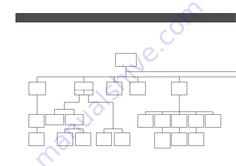
This camera utilizes a user setup menu that is displayed on-screen.
The setup menu contains various items that form a tree-type structure as shown below.
It menu is described in the following section : "2. SETUP OPERATION".

CAM SET UP

Camera
ID
ON/OFF

Camera
ID
Editing

SUPER-D
ON

Camera ID
Display
Position

Manual
Level
Selection

SUPER-D
OFF

Light

Control

ALC      ELC

Manual
Mask Area
Selection

Manual
Level
Selection

INT
Manual
Selection

Shutter

Speed

AGC

ON/OFF

Manual
Mask Area
Selection

VBS
Automatic
Selection

H. Phase
SC. Phase
Manual
Adjustment

H. Phase
Manual
Adjustment

V. Phase
Manual
Adjustment

VS
Automatic
Selection

SYNC

INT/LL

LL
Manual
Selection

VD2
Automatic
Selection

SET UP DISABLE 

SET UP ENABLE 

SET UP

Summary of Contents for WV-CP450

Page 1: ...Colour CCTV Cameras WV CP450 WV CP454 Lens option Before attempting to connect or operate this product please read these instructions completely ...

Page 2: ...alert the user to the pres ence of uninsulated dangerous volt age within the product s enclosure that may be of sufficient magnitude to con stitute a risk of electric shock to per sons ENGLISH VERSION FOR YOUR SAFETY PLEASE READ THE FOLLOWING TEXT CARE FULLY WARNING THIS APPARATUS MUST BE EARTHED IMPORTANT The wires in this mains lead are coloured in accordance with the following code Green and ye...

Page 3: ......

Page 4: ...ler andre normative dokumenter i følge bestemmelserne i direktivene 73 23 EEC og 89 336 EEC Vi deklarerar härmed värt fulla ansvar för att den produkt till vilken denna deklaration hänvisar är i överensstämmelse med standarddokument eller andra normativa dokument som framstölls i Direktiv 73 23 EEC och 89 336 EEC Ilmoitamme yksinomaisella vastuullamme että tuote jota tämä ilmoitus koskee noudattaa...

Page 5: ...D THEIR FUNCTIONS 5 CONNECTIONS 8 FOCUS OR BACK FOCAL ADJUSTMENT 12 INSTALLATION OF CAMERA 13 SET UP 14 1 CAMERA SETUP MENU 14 2 SETUP OPERATION 16 SETTING PROCEDURES 19 PREVENTION OF BLOOMING AND SMEAR 33 SPECIFICATIONS 34 STANDARD ACCESSORIES 36 OPTIONAL ACCESSORIES 36 2 ...

Page 6: ...digital signal processing LSI s This model offers cutting edge technology for advanced video surveillance 3 PREFACE Panasonic s WV CP450 series colour digital camera introduces a new level of high picture quality and high resolution through the use of a 1 3 inch interline trans fer CCD image sensor having 752 horizontal pixels FEATURES 5 480 lines of horizontal resolution 6 High quality picture a ...

Page 7: ...n cleaning the camera body Use a dry cloth to clean the camera when dirty In case the dirt is hard to remove use a mild detergent and wipe gently 5 Clean the CCD faceplate with care Do not clean the CCD with strong or abrasive detergents Use lens tissue or a cotton tipped applicator and ethanol 6 Never face the camera towards the sun Do not aim the camera at bright objects Whether the camera is in...

Page 8: ...IONS 5 SUPERDYNAMIC WV CP450 Hi Z G L 75Ω AC 24V IN DC 12V IN 1 2 VIDEO OUT POWER GND GEN LOCK VIDEO OUT POWER 220ー240V AC 50H GEN LOCK WV CP450 WV CP454 MAJOR OPERATING CONTROLS AND THEIR FUNCTIONS Slide the panel to the left until it locks ...

Page 9: ...is button is used to move the cursor to the right It is also selects the mode and can be used to adjust some levels u Left Button This button is used to move the cursor to the left It also selects the mode and can be used to adjust some levels i Up Button This button is used to move the cursor upward It is also used to select items in the CAM SET UP menu o Set Button This button is used to activat...

Page 10: ... power cord supplied as a standard accessory 5 AC DC Compatible Input Terminal DC 12V IN AC 24V IN This terminal is for connecting the 12 V DC or 24 V AC power supply cord 7 Caution Connect to 12V DC 10 5V 16V or 24V AC 19 5V 28V class 2 power supply only Make sure to connect the grounding lead to the GND terminal when the power is supplied from a 24V AC power source ...

Page 11: ...nnect the AC power cord supplied as standard accessory to the power cord socket of the cam era 2 Connect the AC power cord to an electrical outlet of 220 240V AC 50 Hz Notes Connect the power cord firmly The power cord should be long enough for pan ning and tilting If the cable is too short the power cord plug may be pulled off the camera when the camera pans or tilts B WV CP454 12V DC 24V AC The ...

Page 12: ... 19 5 V 28 V 9 Video Cable 1 It is recommended to use a monitor whose resolu tion is at least equal to that of the camera 2 Set the termination switch to the 75Ω position on the last monitor A Use a 75Ω coaxial cable B Set the termination switch to the 75Ω position on the last monitor and to the Hi Z position on the other monitors Do not change the posi tions after setting C The maximum extensible...

Page 13: ... change the impedance of the cable and cause poor picture quality Installation of Auto Iris Lens Connector Install the lens connector YFE4191J100 when using a video drive ALC lens The installation should be made by qualified ser vice personnel or system installers 1 Cut the iris control cable at the edge of the lens connector to remove the existing lens connector and then remove the outer cable co...

Page 14: ... Control Cable Connector Heat Shrinkable Tubes Connector Cover 1 2 Screws Back focal Adjusting Ring Mounting the Lens Caution Before you mount the lens loosen the two screws on the ring and rotate this ring clockwise until it stops If the ring is not at the end the inner glass or CCD image sensor may be damaged 1 Mount the lens by turning it clockwise on the lens mount of the camera 2 Connect the ...

Page 15: ...llowing adjustment should be made by qualified service personnel or system installers 1 Loosen the screws on the back focal adjusting ring 2 Turn the back focal adjusting ring to the desired position Caution When the C mount lens is mounted do not rotate the ring counterclockwise by force after it If the ring is rotated by force the inner lens or CCD image sensor may be damaged 3 Tighten the screw...

Page 16: ... adapter from the bottom of the camera by removing the two fixing screws Attach the mount adapter to the top as shown in the dia gram then mount the camera on the mounting bracket Make sure that the two original fixing screws are used when mounting the mount adapter as longer length screws may damage inner components 13 Fixing Screws Mount Adapter Mounting at top Mounting at bottom INSTALLATION OF...

Page 17: ...OFF Camera ID Editing SUPER D ON Camera ID Display Position Manual Level Selection SUPER D OFF Light Control ALC ELC Manual Mask Area Selection Manual Level Selection INT Manual Selection Shutter Speed AGC ON OFF Manual Mask Area Selection VBS Automatic Selection H Phase SC Phase Manual Adjustment H Phase Manual Adjustment V Phase Manual Adjustment VS Automatic Selection SYNC INT LL LL Manual Sele...

Page 18: ...5 Manual Level Adjustment Lens Drive Signal Selection DC Video Special menu Chroma Gain AP Gain Pedestal Manual Level Adjustment Manual Mask Area Selection Manual Mask Area Selection White Balance ATW AWC ...

Page 19: ...each time this button is pressed Left Button This button is used to move the cursor to the left Use this button to select or adjust the parameters of the selected item The parame ter changes each time this button is pressed Set Button This button is used to set the determined parameter If the item has its own setting menu indi cates that the setting menu exists press this button to dis play the se...

Page 20: ... other setting menu is displayed displaying the menu is automatically canceled and the mode returns to the normal cam era picture Opening the Setup Menu Press and hold down for a second or longer Editing the CAM SET UP Menu Important Notices When the words SET UP DISABLE appear on the bottom line of the CAM SET UP menu you cannot change the currently active settings This is to pre vent accidental ...

Page 21: ... Notice When the cursor is moved to END and the CAM SET UP menu closed after changing the parame ters the new values are stored in the EEPROM Electric Erasable and Programmable Read Only Memory These values remain valid until new val ues are stored even if the power of the camera is off CAM SET UP CAMERA ID OFF ALC ELC ALC SHUTTER AGC ON SYNC INT WHITE BAL ATW LENS DRIVE DC END SET UP DISABLE CAM ...

Page 22: ...ssing 4 After selecting the character press The selected character appears in the editing area The pointer in the editing area moves to the right automatically at this moment 5 Repeat the steps above until all characters are edited To enter a blank space in the CAMERA ID Move the cursor to SPACE and press To edit a specific character in the CAMERA ID 1 Move the cursor to the editing area by pressi...

Page 23: ...3 Press to fix the position of the CAMERA ID The mode returns to the previous CAMERA ID menu Notes The CAMERA ID stops at the edges of the monitor screen The CAMERA ID moves faster if any of is kept pressed for a second or longer To return to the CAM SET UP menu Move the cursor to RET and press The CAM SET UP menu appears 2 Light Control Setting ALC ELC You can select the light control mode accord...

Page 24: ...lighting which makes the camera picture dark such as a spotlight 1 Press after selecting ALC the ALC CONT menu appears 2 Move the cursor to the SUPER D parameter and select ON 3 If you want to adjust the video output level move the cursor to the I position Adjust to the desired level by pressing or 4 Move the cursor to RET and press to return to the CAM SET UP menu To return to the camera picture ...

Page 25: ...k turns white When the cursor is moved on an area that has already been masked the mask and cur sor start blinking Blinking Blinking 2 2 ALC Mode with SUPER D OFF and ELC Mode Note If ELC is selected set MASK SET according to this procedure 1 Move the cursor to the SUPER D parameter and select OFF When you select ELC SUPER D is not available The item MASK SET appears on the menu ALC CONT BACK LIGH...

Page 26: ...R Note When ON is selected for SUPER D on the ALC CONT menu this item is not available To select electronic shutter speed select OFF for SUPER D in the menu You can select an electronic shutter speed of 1 50 OFF 1 120 1 250 1 500 1 1 000 1 2 000 1 4 000 or 1 10 000 seconds This function is effective to raise the sensitivity in low light conditions when OFF is selected for ALC Move the cursor to th...

Page 27: ...te video or blackburst signal and VS signal B W composite video or composite sync signal The VD2 signal multiplexed vertical drive signal with the composite video output signal from external equipment such as a Matrix Switcher is also acceptable Whenever the VD2 signal is supplied to this camera the camera automatically switches to the VD2 sync mode 1 Move the cursor to the SYNC parameter and sele...

Page 28: ... its own menu for hori zontal and subcarrier phase adjustments When the cable length of the video output or the gen lock input is changed the horizontal and subcarri er phase must be re adjusted 6 The VS gen lock mode has its own menu for hori zontal phase adjustments When the cable length of the video output or the gen lock input is changed the horizontal phase must be re adjust ed 7 The line loc...

Page 29: ... on the oscillo scope SYNC H PHASE I SC COARSE 1 1 4 SC FINE I RET END 8 Adjust the horizontal phase by pressing or The adjustable range is 0 2 0µs 9 Move the cursor to SC COARSE The cursor starts blinking 10 Press or to match the colour hue of the camera s video signal when observed at the out put of the Special Effect Generator SEG or Switcher as closely as possible to the colour of the original...

Page 30: ...COARSE and SC FINE to the val ues preset at the factory press or simultaneously SC COARSE is reset to the factory setting 4 After confirming the cursor is on EXT VS press The phase adjustment menu appears on the monitor 5 2 VS Gen lock Mode EXT VS 1 Move the cursor to the SYNC parameter and select INT 2 Connect the coaxial cable for the composite sync or composite B W video signal to the gen lock ...

Page 31: ...e settings in this menu can be made only when the multiplexed vertical drive signal VD2 is not supplied to the camera SYNC H PHASE I RET END 2 After confirming the cursor is on LL press The vertical phase adjustment menu appears on the monitor 3 Move the cursor to COARSE The cursor starts blinking 4 Supply the video output signal of the camera to be adjusted and the reference camera video output s...

Page 32: ...tane ously COARSE and FINE adjustments are preset at the factory to zero crossing of the AC line phase If the AC line contains noise spike noise etc the stability of the vertical phase of the camera video output signal may be disturbed 6 White Balance Setting WHITE BAL 6 1 Auto Tracing White Balance Mode ATW You can select one of two modes for white balance adjustment as follows ATW Auto Tracing W...

Page 33: ... PUSH SW start blinking to indicate that the white balance is being set Blinking CAM SET UP CAMERA ID OFF ALC ELC ALC SHUTTER AGC ON SYNC INT WHITE BAL AWC PUSH SW LENS DRIVE DC END SET UP ENABLE CAM SET UP CAMERA ID OFF ALC ELC ALC SHUTTER AGC ON SYNC INT WHITE BAL AWC PUSH SW LENS DRIVE DC END SET UP ENABLE 3 When the white balance setting is completed the words PUSH SW stop blinking 4 When you ...

Page 34: ...When you need to set MASK SET re adjust to obtain the optimum amount of red and blue gain 1 Move the cursor to the LENS DRIVE parameter 2 Select DC if you are using the auto iris lens that requires a DC drive signal Select VIDEO if you are using the auto iris lens that requires a video drive signal 7 Lens Drive Signal Selection LENS DRIVE This item is used to select the type of auto iris lens driv...

Page 35: ... the I cursor to adjust the pedestal level black level To reset to the factory settings 1 Move the cursor to the CAMERA RESET parame ter The words PUSH SW start blinking 2 While holding down and press for 2 seconds or longer The camera is reset to the fac tory settings To close the SPECIAL menu and return to the CAM SET UP menu Move the cursor to RET and press To close the SPECIAL menu and return ...

Page 36: ... a spotlight or a surface that reflects bright light smear or blooming may appear Therefore the camera should be operated carefully in the vicinity of extremely bright objects to avoid smear or blooming Bright object Smear PREVENTION OF BLOOMING AND SMEAR ...

Page 37: ...llumination 0 9 lx 0 09 footcandle at F0 75 Equivalent to 3 lx 0 3 footcandle at F1 4 Gain Control Selectable AGC ON or OFF SET UP MENU White Balance Selectable ATW or AWC SET UP MENU Aperture Set Variable SET UP MENU Electronic Light Control Equivalent to continuous variable shutter speed between 1 50 second and 1 10 000 second Back Light Compensation Selectable Preset On or Off SET UP MENU Elect...

Page 38: ...z 5 2W 12V DC 540 mA Dimensions without lens 67 W x 55 H x 123 D mm 2 5 8 W x 2 3 16 H x 4 13 16 D Weights without lens WV CP450 0 405 kg 0 89 lbs without power cord WV CP454 0 405 kg 0 89 lbs Weights and dimensions indicated are approximate Specifications are subject to change without notice ...

Page 39: ... Lenses WV LA2R8C3B WV LA4R5C3B WV LA9C3B WV LA210C3 WV LA408C3 WV LA908C3 WV LZ61 10 WV LZ62 2 WV LF4R5C3A WV LF9C3A STANDARD ACCESSORIES Body Cap 1 pc ALC Lens Connector YFE4191J100 1 pc AC Power Cord for only WV CP450 1 pc ...

Page 40: ...Matsushita Electric Industrial Co Ltd Central P O Box 288 Osaka 530 91 Japan N0797 1087 YWV8QA4715BN Printed in Japan N 30 Gedruckt in Japan Imprimé au Japon Impreso en Japón ...

Reviews: