background image

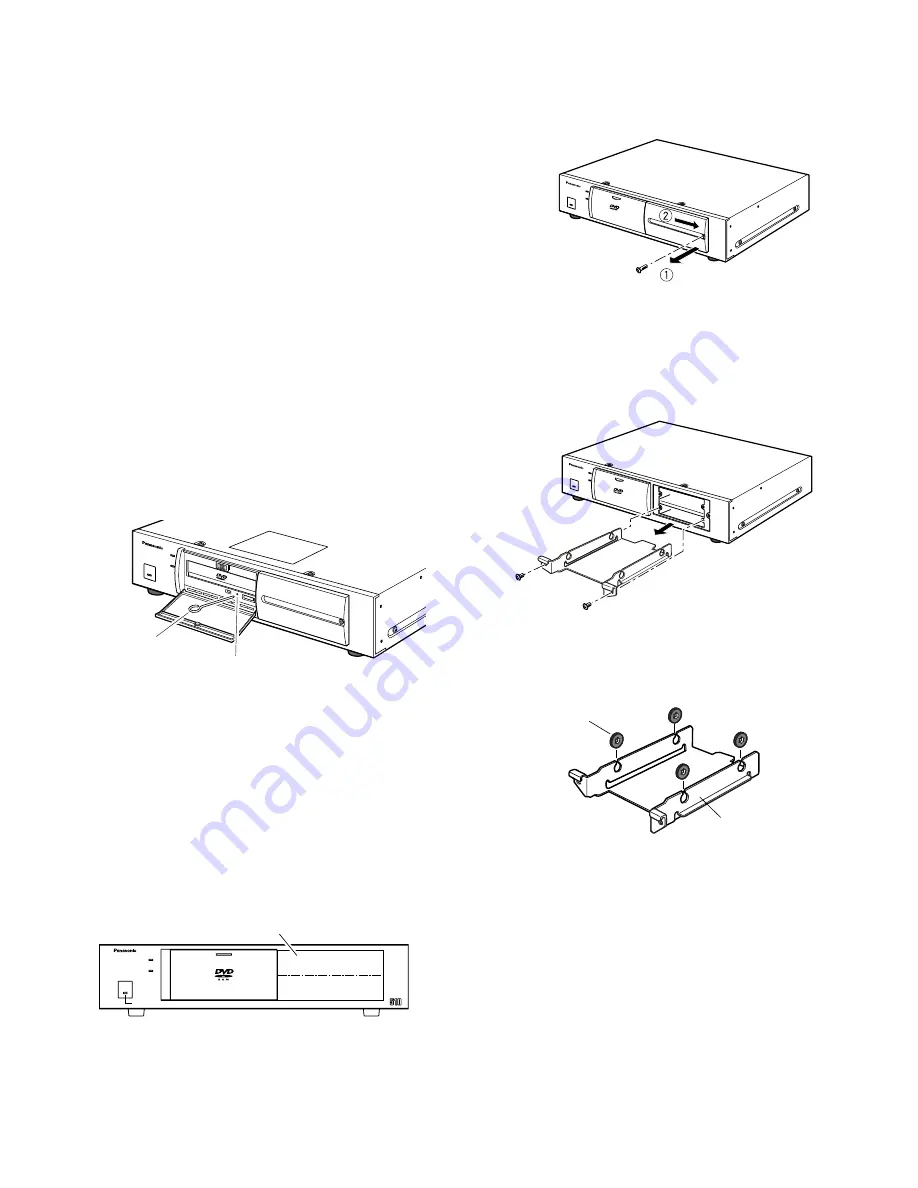
2. Remove the HDD lid.

2-1 Loosen the HDD lid fixing screw.
2-2 Slide the HDD lid to the right and remove the

screw.

3. Remove the HDD brackets #1 and #2.

3-1 Loosen two screws.
3-2 Pull bracket #1 out of the bay.

Note:

Keep the four removed fixing screws for

use in step 8.

4. Insert the four HDD absorbers (supplied) so that the

grooves are caught in the fixing bracket.

5. Prepare an HDD unit.

Notes:

• Put your hand on a metallic surface to discharge

static electricity before taking out the dampers
from the case.

• Place the case with the HDD on a soft surface

such as a cushion mat with the circuit board
side up to discharge static electricity.

6. Hold the HDD on both sides and place it on the fix-

ing bracket. Then fasten it with the four screws,
sleeves and earth lugs.

Note:

Never use an electric screwdriver to prevent

shock.

-6-

Installing the Optional Hard

Disk

A maximum of two HDD units (procured locally) can be
installed in the DVD Extension Unit. The following
describes how to install HDD #1 (MASTER). To install #2
HDD, repeat the steps described for #1 HDD.
Install the HDD units in the bays in the following order.
Neveer skip or reverse the order of the HDD units.

1. Turn on the power switch located on the rear panel

of the DVD Extension Unit and disconnect the power
cord from an AC outlet.

HDD #1

HDD #2

WJ-HDE

Unit

Extension

HDD

HDD

2

1

OPERATE LED WILL CHANGE TO ORANGE
IF THE INSIDE TEMPERATURE EXCEEDS OR FALLS BELOW THE LIMIT.

OPERATE

HDD Positions Inside the Lid

HDD

HDD

R A M

R A M

HDD

HDD

Removal of the DVD-RAM
disk from the DVD
Extension Unit

Before removing the DVD-RAM disk from the DVD
Extension Unit, carry out the following two steps with the
DVD recorder.

1. Delete the menu and list display screens.
2. Press the COPY button for 2 seconds or more

and confirm that ”DVD UNLOCKED” is dis-
played in the center of the monitor screen.

1. Press the DVD-RAM lid to open on the front of the

DVD Extension Unit and press the OPEN/CLOSE
button.

2. The DVD-RAM tray slides out. Remove the disk.

Note:

Emergency eject

If you are unable for some reason to open the
drive with the OPEN/CLOSE button, first make
sure that the power of the DVD Extension Unit is
turned off, and then open the drive by inserting
the supplied eject pin into the eject hole on the
front of the drive.

R O

M

Eject Pin (supplied)

Eject Hole

Absorber x 4
(supplied)

Fixing Bracket

Summary of Contents for WJHDE510 - EXTENTION BOARD

Page 1: ... important operating and maintenance servicing instructions in the literature accompanying the appli ance CAUTION TO REDUCE THE RISK OF ELECTRIC SHOCK DO NOT REMOVE COVER OR BACK NO USER SERVICEABLE PARTS INSIDE REFER SERVICING TO QUALIFIED SERVICE PERSONNEL CAUTION RISK OF ELECTRIC SHOCK DO NOT OPEN SA 1965 SA 1966 NOTE This equipment has been tested and found to comply with the limits for a Clas...

Page 2: ...ve Avoid condensation on the surface of the HDD and DVD RAM disk Be sure to install the DVD Extension Unit horizontal ly General The WJ HDE510 is a DVD Extension Unit for connection with the WJ HD500 Digital Disk Recorder for copying or backing up recorded data The system can be extend ed by connecting up to 6 extension units in an SCSI chain while the DVD extension unit containing up to two HDDs ...

Page 3: ...OPEN CLOSE button to slide out the tray 7 Press the OPEN CLOSE button again to slide in the tray 8 Close the DVD RAM lid Note The optimum cleaning frequency differs depending on the usage environment and conditions It is recommended though to clean the drive once every one to four months Disk tray DVD RAM lid Cleaning disc BUSY indicator OPEN CLOSE button Handling DVD RAM disks Avoid exposure to d...

Page 4: ...used for insertion or removal of the DVD RAM disk while the DVD RAM lid is opened o Hard Disk Detection switch HDD INSTALLED NOT INSTALLED Detects an optional HDD when one is installed 0 SCSI Output connector EXT OUT Connect another Extension Unit with an SCSI cable 1 SCSI Input connector EXT IN Connect the WJ HD500 or another Extension Unit with an SCSI cable 2 SCSI ID switch SCSI ID Press the or...

Page 5: ...t this terminal with the other equipment s SIGNAL GND to avoid possible grounding loop and noise if required INSTALLATION The installations described below should be made by qualified service personnel or system installers Inserting the DVD RAM disk into the DVD Extension Unit A new DVD RAM disk needs to be formatted on a DVD recorder For formatting information refer to the operat ing instruction ...

Page 6: ...in the bays in the following order Neveer skip or reverse the order of the HDD units 1 Turn on the power switch located on the rear panel of the DVD Extension Unit and disconnect the power cord from an AC outlet HDD 1 HDD 2 WJ HDE Unit Extension HDD HDD 2 1 OPERATE LED WILL CHANGE TO ORANGE IF THE INSIDE TEMPERATURE EXCEEDS OR FALLS BELOW THE LIMIT OPERATE HDD Positions Inside the Lid HD D HD D R ...

Page 7: ...D500 and the COPY IN port on the 1st DVD Extension Unit with the supplied WJ HDE510 SCSI cable Plug the cable end with magnetic core into the COPY port and the other ends into the COPY IN port 2 Connect between the EXT STORAGE port on the WJ HD500 and the EXT IN port on the 2nd Extension Unit with the supplied WJ HDE510 SCSI cable Plug the cable end with magnetic core into the EXT STRAGE port and ...

Page 8: ...Extension Unit G THERMAL ERROR OUT NC Error Connection Connect each of the error outputs to the CONTROL port on the rear panel of the WJ HD500 as shown below The WJ HD500 will display a thermal error on the monitor screen 1 2 3 4 MODE ON Switch Settings 1 Set MODE switch 2 on the rear of the WJ HD500 to OFF when connecting a DVD Extension Unit without an optional HDD Set the MODE switch to ON If t...

Page 9: ...5 5 4 4 3 2 2 3 1 1 SIGNAL GND SPOT OUT IN EXT STORAGE COPY CONTROL ALARM VIDEO MODE DATA REMOTE WV CU50 SERIAL POWER ON AC IN OFF IN OUT OUT MULTISCREENOUT AUDIO SCSI ID TERMINATOR 1 GND ON OFF SIGNAL AC IN POWER EXT IN COPY IN EXT OUT G NC THERMAL ERROROUT ON OFF HDD INSTALLED NOT INSTALLED COPY port CONTROL port SIGNAL GND POWER AC IN SCSI ID EXT OUT EXT IN TERMINATOR GND THERMAL ERROR OUT NC O...

Page 10: ...2 Place the rack mounting brackets on both sides of the DVD Extension Unit and tighten with the four supplied screws M4x10 3 Install the DVD Extension Unit with the rack mounting brackets in the rack securing it with four screws not included Cautions When mounting a DVD Extension Unit together with other appli ances in a rack it may be influenced by the power transformer etc of some units such as ...

Page 11: ...ing or playback is completed 6 7 12 Confirm the type of DVD RAM disk Phenomenon Cause What to do No power is supplied Power cord is not firmly connect ed Securely plug the cord into AC outlet and AC inlet Thermal error OPERATE indicator lights in orange DVD RAM drive is not recog nized Ambient temperature is too low Ventilation openings or fan is blocked Use the unit within 5 C to 45 C Remove obst...

Page 12: ... 6838 Midwest 1707 North Randall Road Elgin IL 60123 847 468 5211 Western 6550 Katella Ave Cypress CA 90630 714 373 7840 2001 Matsushita Communication Industrial Co Ltd All rights reserved Accessories Power Cord 1 pc DVD Viewer Software CD ROM 1 pc SCSI Cables Half pitch 50 pin D sub 2 pcs Rack Mounting Brackets 2 pcs Bracket Fixing Screws 4 pcs HDD Fixing Screws 8 pcs Absorbers 8 pcs Sleeves 8 pc...

Reviews: