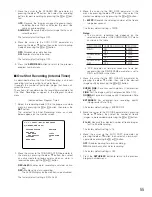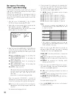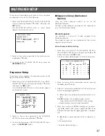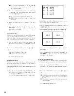
69
●
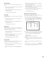
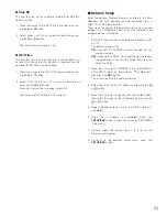
Parity Check
This item lets you set the parity bit for RS-485 communica-
tion.
1. Move the cursor to the PARITY CHECK parameter by
pressing the
D
or
C
button.
2. Select NONE, EVEN or ODD for parity check by press-
ing the
+
or
-
button.
The factory default setting is NONE.
●
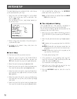
Stop Bit
This item lets you set the number of stop bits for RS-485
communication.
1. Move the cursor to the STOP BIT parameter by press-
ing the
D
or
C
button.
2. Select either 1 or 2 for the number of stop bits by press-
ing the
+
or
-
button.
The factory default setting is 1 bit.
●
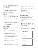
Wait Time
This item lets you set the waiting time in milli-seconds (ms)
to retry after confirming that no data is received from the
controller for RS-485 communication.
1. Move the cursor to the WAIT TIME parameter by press-
ing the
D
or
C
button.
2. Select OFF, 100, 200, 400, or 1 000 ms for the wait time
by pressing the
+
or
-
button.
When no transmission is needed, select OFF.
The factory default setting is OFF (no retry).
●
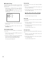
Alarm Data
This item lets you enable or disable notification of the alarm
data received to the controller (Unit Number 1).
1. Move the cursor to the ALARM DATA parameter by
pressing the
D
or
C
button.
2. Select the desired mode by pressing the
+
or
-
but-
ton.
OFF:
Select this parameter if the system controller is
not connected to the system.
0S:
Each time an alarm is received, it is transmitted to
the system controller.
1S:
The received alarm is stored for 1 second, and that
data is sent to the system controller.
5S:
The received alarm is stored for 5 seconds, and
that data is sent to the system controller.
The factory default setting is 1S.
●
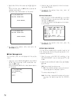
Input (Camera) Number Setup
This item lets you assign numbers for the input from the
system cameras for RS-485 communication.
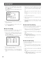
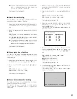
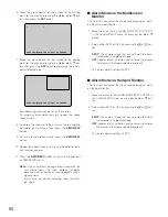
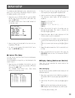
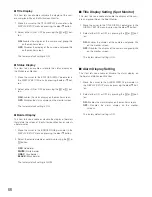
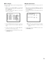
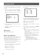
1. Move the cursor to CAMERA NUMBER SETUP by
pressing the
D
or
C
button, then press the
SET
button.
The CAMERA NUMBER SETUP table shown below
appears on the monitor screen.
2. Move the cursor to the input (CAM-PORT) parameter to
edit by pressing the
D
,
C
,
A
or
B
button, then select
a camera number by pressing the
+
or
-
button.
---:
No assignment.
001 - 128:
Assigns the selected number.
Note:
Make sure not to assign the same number to
more than one system camera for RS-485 communi-
cation.
3. Repeat the above procedure to edit other input para-
meters.
4. After completing the settings, press the
SETUP/ESC
button to return to the previous setup menu.
8-1-1 CAMERA NUMBER SETUP
CAM-PORT CAM NO. CAM-PORT CAM NO.
1 001 9 009
2 002 10 010
3 003 11 011
4 004 12 012
5 005 13 013
6 006 14 014
7 007 15 015
8 008 16 016
Summary of Contents for WJ-HD500B
Page 26: ...26 ...
Page 27: ...27 PREPARATIONS ...
Page 40: ...40 ...
Page 41: ...41 SETUP PROCEDURES ...
Page 78: ...78 ...
Page 79: ...79 OPERATING PROCEDURES ...

