80
14.4 How To Adjust Water Flow Rate
Before adjust the water flow rate, make sure that the total water volume in the installation is 50 litres minimum for
heating side. The default setting is SPEED 4 (Only for WH-MHF09G3E8) and SPEED
5 for WH-MHF12G9E8. Please ensure the minimum flow rate is not less than 13 l/min and not more than 50 l/min.
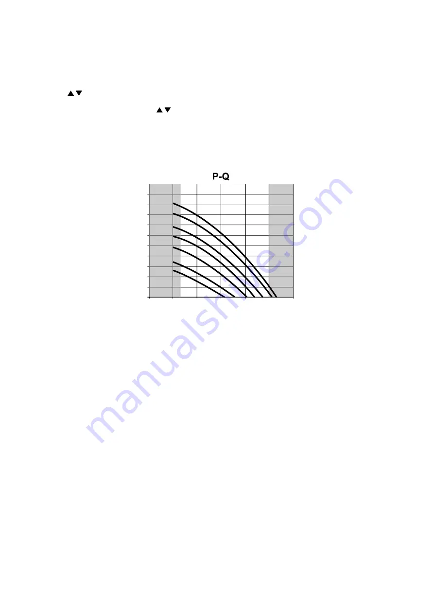
The available external static pressure (kPa) in function of the water flow rate (l/min) is shown in the P-Q graph.
Depend on the hydraulic system pressure loss and type, the water flow rate can be adjusted by remote control.
1 When the Air-to-Water Heatpump is in stop operation, press SERVICE button for 5 seconds.
2 Press / button to select menu S02 (PUMP SPEED ADJUST MODE) and press SET button to confirm the
menu.
3 Press SELECT button then press / button to change pump speed and press SET button to confirm the
pump speed.
4 Press OFF/ON button to exit PUMP SPEED ADJUST MODE.
During PUMP SPEED ADJUST MODE, we can select AIR PURGE function by pressing FORCE button.
In AIR PURGE function, the pump will operate ON and OFF for 10 minutes to purge the air in the hydraulic system.
Press again the FORCE button to exit AIR PURGE function. PUMP SPEED ADJUST
MODE will stop operation.
0
1013
20
30
40
50
60
WATER FLOW RATE (L/min)
110
100
90
80
70
60
50
40
30
20
10
0
1
2
3
4
5
6
7
E
X
TERNAL STATIC PRESS
URE
(
kPa)
NO
T
APPL
IC
A
B
L
E
R
ANG
E
NO
T
APPL
IC
A
B
L
E
R
ANG
E
14.5 Expansion Vessel Pre Pressure Checking
Expansion Vessel with 10 L air capacity and initial pressure of 1 bar is installed in this Mono bloc unit.
Total amount of water in system should be below 200 L.
(Note: This amount of water is not include the tank unit volume)
If total amount of water is more than 200L, please install additional expansion vessel (field supply).
Please keep the installation height difference of system water circuit within 10 m.
(Inner volume of same Mono bloc unit is about 5 L)
Summary of Contents for WH-MHF09G3E8
Page 32: ...32 10 1 2 Solar Printed Circuit Board Optional ...
Page 33: ...33 10 2 Refrigerant System 10 2 1 Main Printed Circuit Board ...
Page 34: ...34 10 2 1 1 Noise Filter Printed Circuit Board ...
Page 47: ...47 Heat Mode Operation Time Chart ...
Page 49: ...49 ...
Page 50: ...50 ...
Page 56: ...56 ...
Page 57: ...57 ...
Page 58: ...58 ...
Page 127: ...127 17 3 To Remove The Cabinet Rear Plate 17 4 To Remove Pressure Gauge 17 5 To Remove RCCB ...
Page 138: ...138 19 2 Water System 44 46 17 16 4 34 42 18 43 3 33 9 1 45 45 47 2 35 48 36 19 ...


