


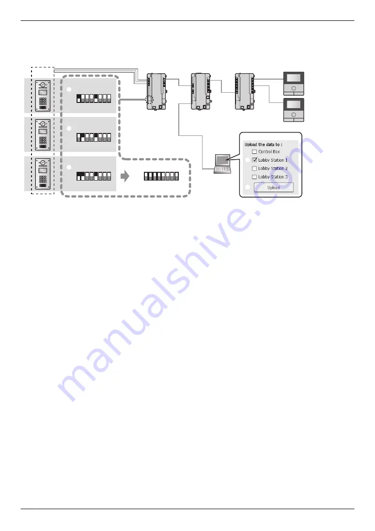
Example of an extension box connected to port 1 of the control box ([Lobby Station 1] must be selected in
the Setup tool)
The following procedure is an example of how to configure settings for the system shown in the following illustration.
Extension box
(
Up to
3)
Lobby station
(Up to 18: 6 lobby stations per extension box with max. of 3 extension boxes)
PC
Distribution box
Main monitor
Control box (1)
PC setup tool
2
3
DIP switch
DIP switch
1 2 3 4 5 6 7 8
ON
OFF
1 2 3 4 5 6 7 8
ON
OFF
1 2 3 4 5 6 7 8
ON
OFF
6
1 2 3 4 5 6 7 8
ON
OFF
1
1st lobby station 1
4
2nd lobby station 1
5
3rd lobby station 1
Lobby station
1 group
(off)
Important:
R
Settings for each lobby station connected to an extension box must be configured separately.
R
DIP switches on the extension box are used to determine which lobby station that settings are uploaded
to. The number 6 - 8 switches must always be set to the "off" position. (For a list of DIP switch settings,
see page 71.)
R
When you are using the PC setup tool with the extension box connected to the PC, set the DIP switches
according to the instructions in 5.6.2 Extension box DIP switch settings (Page 71) before doing the
following operations.
–
downloading from a lobby station
–
uploading to a lobby station
–
checking lobby station connections (for systems that support enhanced features version 2 or later
(page 92))
1. DIP switch setting of extension box:
Set the DIP switches to the settings shown under "
A
1st lobby station 1".
2. PC setup tool: Load and edit the data
Start the setup tool. In the
[Load and edit the data]
section, configure the required
[Room settings]
and
[General
settings]
for
[Lobby Station 1]
.
3. PC setup tool: Upload the data to device
In the
[Upload the data to device]
section, select
[Lobby Station 1]
as shown next to "
B
" under "PC setup
tool", and then click
[Upload]
as shown next to "
C
" under "PC setup tool".
4. DIP switch setting of extension box:
Set the DIP switches to the settings shown under "
D
2nd lobby station 1".
5. PC setup tool: Upload the data to device
6. DIP switch setting of extension box:
Set the DIP switches to the settings shown under "
E
3rd lobby station 1".
7. PC setup tool: Upload the data to device
8. DIP switch setting of extension box:
After configuring all the lobby stations, set all the DIP switches of the extension box to the "off" position as shown
under "
F
".
70
5. Programming


