15
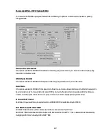
Single Step Down
- Single steps the badge push-up mechanism down. . The number of steps to the home
position is displayed in the step counter window to the left of this function.
Overrun button
- This function causes the badge push-up mechanism to travel to the number code read position
or to the irradiate position.
Origin button
- This function causes the badge push-up mechanism to travel to the NCR position or the home
position.
Vert Home Position indicator
- Monitors the status of the Home Position Sensor RSR1. When the badge
push-up mechanism is at the home position, this sensor is logic 1.
NCR Position Detect indicator
- Monitors the status of the NCR Position Sensor RSR2. When the badge push-
up mechanism is at the NCR position, this sensor is logic 1.
Irradiate Position indicator
- Monitors the status of the Irradiate Position Sensor RSR3. When the badge push-up
mechanism is at the irradiate position, this sensor is logic 1.
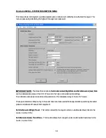
Mode Reader Check MENU -- BADGE NUMBER CODE READ MENU
This menu tests the badge number code read functions of the Irradiator Irradiator.
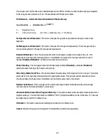
NCR Lamp Off\On control
- This output signal turns on the lamp array in the number code reader. “On” position
turns on the lamp array so that the punched number code data can be read. “Off” position turns off the lamp array.
Read NCR button
- This function causes a badge to travel to the number code read position where the badge
number code is read. The badge number code data is continuously decoded, formatted and displayed in the
NCR window. Then, the badge is moved back to the home position.
N1 Parity Error indicator
- This input signal monitors the number code data punched in row 0 of the TL badge.
If a bit position (0-19) is punched (hole), this signal will be logic 1. If a bit position (0-19) is not punched (closed), this
signal will be logic 0.
N2 Parity Error indicator
- This input signal monitors the number code data punched in row 1 of the TL badge.
If a bit position (0-19) is punched (hole), this signal will be logic 1. If a bit position (0-19) is not punched (closed), this
signal will be logic 0.
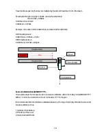
Solenoid Test –
This switch tests the solenoid. If enabled, the irradiator is in unattenuated (high dose) position
and if disabled, the irradiator is in attenuated (low dose) position.
Door Open indicator
- This input signal monitors if UD-794 door is open or not.
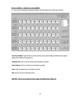
Load Tray button
- This function loads tray into starting position.


