


34
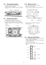
9.27. Remove the K-Board
1. Remove the Contact metal bottom. (See section 9.26.)
2. Remove the screw (
×
1 ).
3. Remove the claw (
×
1 ).
4. Disconnect the connector (K1) and Remove the K-Board
from LED Panel.
9.28. Remove the V-Board
1. Remove the Contact metal bottom. (See section 9.26.)
2. Remove the screw (
×
1
each).
3. Disconnect the connector (V1 each) and Remove the V-
Board from the Emitter fixing metal.
9.29. Replace the plasma panel
Caution:
A new plasma panel itself without Hanger metals is
fragile.
To avoid the damage to new plasma panel, carry a new
plasma panel taking hold of the Hanger metals after
assembling the Hanger metals and the One leg bracket.
1. Place a carton box packed a new plasma panel on the flat
surface of the work bench.
2. Open a box and without taking a new plasma panel;
Attach the C1, C2, C3, C4, C5 and the C6-Board, connect
the flexible cables from the plasma panel to the C1, C2,
C3, C4, C5 and the C6-Board, and fit the flexible cable
holders.
3. Attach the Hanger metals and the One leg bracket to the
new plasma panel.
4. Place the plasma panel on the servicing stand taking hold
of the Hanger metals.
5. Attach the cabinet assy and each P.C.Board and so on, to
the new plasma panel.
Summary of Contents for TXP50VT20L
Page 24: ...24 7 4 No Picture ...
Page 46: ...46 ...
Page 48: ...48 12 3 Wiring 2 12 4 Wiring 3 ...
Page 49: ...49 12 5 Wiring 4 ...
Page 50: ...50 12 6 Wiring 5 ...
Page 51: ...51 13 Schematic Diagram 13 1 Schematic Diagram Note ...
Page 104: ...104 A B C D E F G H I 1 2 3 4 5 6 P BOARD COMPONENT SIDE ETX2MM806MVH ...
Page 122: ...122 15 1 2 Exploded View 2 ...
Page 123: ...123 15 1 3 Packing 1 ...
Page 124: ...124 15 1 4 Packing 2 ...
Page 125: ...125 15 1 5 Mechanical Replacement Parts List ...
Page 129: ...129 15 2 Electrical Replacement Parts List 15 2 1 Replacement Parts List Notes ...