


28
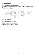
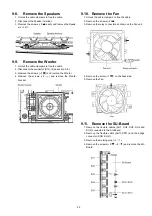
9.5.
Remove the XS-Board
1. Unlock the cable clampers to free the cable.
2. Disconnect the flexible cable (XS3).
3. Remove the screws (
×
3
) and remove the XS-Board
unit.
4. Remove the screws (
×
3
) and remove the XS-Board.
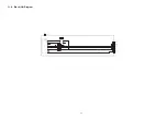
9.6.
Remove the Tuner unit
1. Remove the Side terminal cover and the Side shield
metal. (See section 9.4.)
2. Remove the XW-Board. (See section 9.5.)
3. Unlock the cable clampers to free the cable.
4. Disconnect the connectors (A1, A3, A6, A7, A8, A11, A12
and A20).
5. Disconnect the flexible cables (A31 and A88A).
6. Remove the screws (
×
2
) and remove the Tuner unit.
9.7.
Remove the A-Board
1. Remove the Tuner unit. (See section 9.6.)
2. Remove the screws (
×
3
) and remove the A-Board.
Summary of Contents for TXP50VT20L
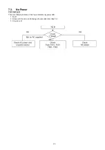
Page 24: ...24 7 4 No Picture ...
Page 46: ...46 ...
Page 48: ...48 12 3 Wiring 2 12 4 Wiring 3 ...
Page 49: ...49 12 5 Wiring 4 ...
Page 50: ...50 12 6 Wiring 5 ...
Page 51: ...51 13 Schematic Diagram 13 1 Schematic Diagram Note ...
Page 104: ...104 A B C D E F G H I 1 2 3 4 5 6 P BOARD COMPONENT SIDE ETX2MM806MVH ...
Page 122: ...122 15 1 2 Exploded View 2 ...
Page 123: ...123 15 1 3 Packing 1 ...
Page 124: ...124 15 1 4 Packing 2 ...
Page 125: ...125 15 1 5 Mechanical Replacement Parts List ...
Page 129: ...129 15 2 Electrical Replacement Parts List 15 2 1 Replacement Parts List Notes ...