


29
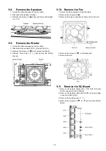
9.8.
Remove the Speakers
1. Unlock the cable clampers to free the cable.
2. Disconnect the Speaker terminal.
3. Remove the screws (
×
2
each) and remove the Speak-
ers (L, R).
9.9.
Remove the Woofer
1. Unlock the cable clampers to free the cable.
2. Disconnect the connector (A12). (See section 9.6.)
3. Remove the screws (
×
3
) and remove the Woofer.
4. Remove the screws (
×
2
) and remove the Woofer
bracket.
9.10. Remove the Fan
1. Unlock the cable clampers to free the cable.
2. Remove the screws (
×
2 ).
3. Remove the relay connectors and remove the Fan unit.
4. Remove the screw (
×
1
) on the back side.
5. Remove the Fan.
9.11. Remove the SU-Board
1. Remove the flexible cables (SU1, SU2, SU3, SU4 and
SU5) connected to the SU-Board.
2. Remove the flexible cable (SU11-SD11) and the bridge
connector (SC41-SU41).
3. Remove the molding prop (
×
1 ).
4. Remove the screws (
×
2 ,
×
2
) and remove the SU-
Board.
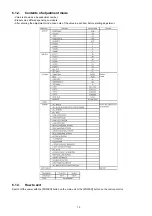
Summary of Contents for TXP50VT20L
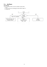
Page 24: ...24 7 4 No Picture ...
Page 46: ...46 ...
Page 48: ...48 12 3 Wiring 2 12 4 Wiring 3 ...
Page 49: ...49 12 5 Wiring 4 ...
Page 50: ...50 12 6 Wiring 5 ...
Page 51: ...51 13 Schematic Diagram 13 1 Schematic Diagram Note ...
Page 104: ...104 A B C D E F G H I 1 2 3 4 5 6 P BOARD COMPONENT SIDE ETX2MM806MVH ...
Page 122: ...122 15 1 2 Exploded View 2 ...
Page 123: ...123 15 1 3 Packing 1 ...
Page 124: ...124 15 1 4 Packing 2 ...
Page 125: ...125 15 1 5 Mechanical Replacement Parts List ...
Page 129: ...129 15 2 Electrical Replacement Parts List 15 2 1 Replacement Parts List Notes ...