6.2.
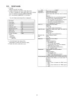
Option - Mirror
P icture can be reve rsed left and right o r up and down.
00 : D e fa ult (N o rm a l picture is d isp la ye d )
01 : P icture is reve rsed left and right.
02 : P icture is reversed up and down.
H int : If th e d e fe ctive s y m p to m (e.g. V ertical ba r or H o rizon tal bar) is m oved by selectio n o f this m irror, the po ssib le cau se is in
A -b o a rd o r D-board.
6.3.
Service tool mode
6.3.1.
How to access
1. S e le c t [S R V -T O O L] in S ervice Mode.
2. P ress [O K ] button on th e rem o te control.
Display of TD2Microcode version —
Display of Flash ROM maker code -
Display of SOS History ----------------
SRV-TOOL
TD2Microcode:00500910
Flash ROM : 1 - 227E
PTCT : 00 . 00 . 00 . 00 . 00
Time 00000:40
On/Off 0000022
POWER ON TIME/COUNT
Press [MUTE] button (3 sec)
6.3.2.
Display of SOS History
S O S H isto ry (N u m b e r o f LE D blinking ) indication.
F rom left side; Last SO S, before Last, th re e o ccu rre n ce before, 2nd occu rre n ce a fte r shipm ent, 1 st o ccu rre n ce a fte r shipm ent.
T his in dication w ill be cleared by [S e lf-c h e c k in dication and forced to fa c to ry s h ip m e n t setting].
6.3.3.
POWER ON Time, On/Off
N ote : To displa y T IM E /C O U N T m enu, hig h lig h t position, the n press M U T E fo r 3 sec.
T im e : C u m u la tiv e p o w e r on tim e, in dicated ho ur : m inute by de cim al
O n /O ff : N u m b e r o f O n /O ff sw itch ing by de cim al
N ote : T his in dication w ill not be cleared by e ith e r o f th e s e lf-ch e cks o r an y o th e r com m and.
6.3.4.
Exit
1. D is c o n n e c t th e A C cord from w a ll o u tle t o r sw itch o ff th e p o w e r w ith [ P o w e r ] button on the m ain unit.
15
Summary of Contents for TX-PR65VT20
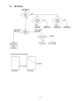
Page 23: ...7 4 No Picture 23 ...
Page 38: ...38 ...
Page 39: ...11 Block Diagram 11 1 Main Block Diagram 39 ...
Page 40: ...11 2 Block 1 5 Diagram 40 ...
Page 41: ...Block 2 5 Diagram ...
Page 42: ...11 4 Block 3 5 Diagram г а P O W E R S U P P LY 42 ...
Page 44: ...11 6 Block 5 5 Diagram S C S C A N D R IV E 44 ...
Page 45: ......
Page 47: ...12 3 Wiring 2 46 ...
Page 48: ...12 5 Wiring 4 12 6 Wiring 5 47 ...
Page 49: ...12 7 Wiring 6 48 ...
Page 52: ...13 2 P MAIN Board 1 3 Schematic Diagram 50 ...
Page 53: ...13 3 P MAIN Board 2 3 Schematic Diagram A B C D E F i 2 3 4 5 6 7 51 ...
Page 55: ...13 5 P SUB Board Schematic Diagram 53 ...
Page 57: ...13 7 A Board 2 25 Schematic Diagram A A BOARD 2 25 Peaks DEST 55 ...
Page 61: ...41 4 2 4 3 4 4 4 5 58 ...
Page 63: ...A A BOARD 7 25 GenX8 13 12 A Board 7 25 Schematic Diagram 5 5 5 6 5 7 5 8 5 9 60 ...
Page 64: ...60 61 62 6 3 ...
Page 67: ...Peaks Com mon 7 8 79 8 0 81 ...
Page 69: ...86 8 7 88 89 9 0 63 ...
Page 76: ...131 1 3 2 1 3 3 1 3 4 13 5 68 ...
Page 85: ...IC 5 5 0 0 C0DBAYY0071 5 2 0 4 2 0 5 2 0 6 2 0 7 ...
Page 89: ...5 1 6 1 7 1 8 1 9 79 ...
Page 90: ...13 32 D Board 2 5 Schematic Diagram 10 1 11 1 12 1 13 1 14 1 15 1 16 1 1 7 1 18 80 ...
Page 91: ...13 33 D Board 3 5 Schematic Diagram 19 1 2 0 1 21 1 2 2 1 2 3 1 2 4 1 2 5 1 2 6 1 2 7 81 ...
Page 92: ...13 34 D Board 4 5 Schematic Diagram 2 8 2 9 30 31 32 3 3 3 4 3 5 3 6 82 ...
Page 93: ...13 35 D Board 5 5 Schematic Diagram 37 38 3 9 4 0 41 4 2 4 3 4 4 4 5 83 ...
Page 94: ...13 36 C1 Board Schematic Diagram A B C D E A C1 BOARD TXNC11LPUJ C20 F 1 2 3 4 5 84 ...
Page 97: ...13 39 C3 Board 1 2 Schematic Diagram F 1 2 3 4 5 87 ...
Page 98: ...13 40 C3 Board 2 2 Schematic Diagram A 10 I 11 12 13 14 C3 BOARD TXNC31 LPUJ 2 2 88 ...
Page 99: ...15 16 17 18 ...
Page 100: ...13 41 C4 Board Schematic Diagram A B C D E A C4 BOARD TXNC41LPUJ C50 F 1 2 3 89 ...
Page 103: ...13 44 C6 Board 1 2 Schematic Diagram A C6 BOARD TXNC61LPUJ 1 2 A 92 ...
Page 105: ...ь fbtq CA14 1 ь I CA15 я 15 16 17 18 ...
Page 107: ...13 47 SC Board 2 4 Schematic Diagram 10 I 11 1 12 1 13 1 14 1 1 5 1 16 1 17 1 18 95 ...
Page 108: ...13 48 SC Board 3 4 Schematic Diagram 19 1 2 0 1 21 1 2 2 1 2 3 1 2 4 1 2 5 1 2 6 1 2 7 96 ...
Page 109: ...13 49 SC Board 4 4 Schematic Diagram 2 8 2 9 3 0 31 3 2 3 3 3 4 3 5 3 6 97 ...
Page 115: ...P MAIN BOARD COMPONENT SIDE ETX2MM813MDM 6 5 4 3 2 1 A I B I C I D I E I F I G I H I I 102 ...
Page 119: ...14 4 A Board A BOARD FOIL SIDE A PR65VT20 т а B G 6 5 4 3 2 1 E F H 106 ...
Page 120: ...A BOARD COMPONENT SIDE A PR65VT20 6 5 4 3 2 1 A I B I C I D I E I F I G I H I I 107 ...
Page 121: ...14 5 D Board 108 ...
Page 122: ...6 D BOARD COMPONENT SIDE TZTNP01LCUE A I В I С I D ...
Page 123: ......
Page 124: ...14 6 C1 Board C1 BOARD COMPONENT SIDE TXNC11LPUJ 1 A I B I C I D I E I F I G I H I I 110 ...
Page 126: ...14 8 C3 Board C3 BOARD FOIL SIDE TXNC31LPUJ 6 5 4 3 1 A I B I C I D I E I F I G I H I I 112 ...
Page 127: ...14 9 C4 Board 113 ...
Page 129: ...14 11 C6 Board 3 C6 BOARD COMPONENT SIDE TXNC61LPUJ 1 A I B I C I D I E I F I G I H I I 115 ...
Page 130: ...14 12 SC Board SC BOARD FOIL SIDE TXNSC1LPUJ В 116 ...
Page 131: ......
Page 132: ... SC BOARD COMPONENT SIDE TXNSC1LPUJ 6 5 4 3 2 1 A I B I C I D I E I F I G I H I I 117 ...
Page 133: ...14 13 SS Board 1 A I B I C I D I E I F I G I H I I 118 ...
Page 134: ...1 A I B I C I D I E I F I G I H I I 119 ...
Page 137: ...15 1 2 Exploded View 2 122 ...
Page 138: ...123 ...
Page 139: ...15 1 4 Packing 2 124 ...

