6.4.
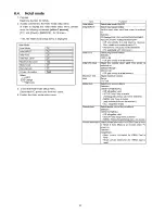
Hotel mode
1. P urpose
R e strict a fun ction fo r hotels.
2. A c c e s s com m a n d to th e Hotel m ode setu p m enu
In o rd e r to d is p la y th e Hotel m ode setu p menu, please
e n te r th e follow ing com m a nd
(w ith in 2 s e c o n d )
.
[T V ] : Vol. [D o w n ] + [R E M O T E ] : AV (3 tim e s)
Then, th e Hotel m ode setu p m enu is displayed.
Hotel Mode
Hotel Mode
1
Off______________________|
Initial INPUT
1
Off
1
Intial POS
1
Off
1
Intial VOL Level
Г о т
|
Maximum Vol Level
1
100
I
Button Lock
Г о т
|
Remote Lock
I Off
I
Private Information
| Keep
|
Select
^ O E X I T
(<юй- Change
" °R E TU R N
3. To exit th e Hotel m ode setup m enu
D is c o n n e c t A C po w e r cord fro m w a ll outlet.
4. Explain th e Hotel m ode setu p m enu
item
Function
Hotel Mode
Select hotel mode ON/OFF
Initial INPUT
Select input signal modes.
Set the input, when each time power is switched
on.
Selection :
Off/Analog/DVB-T/AV1/AV2/AV2S/AV3/COMPO-
NENT/PC/HDMI1/HDMI2/HDMI3/HDMI4
• Off: give priority to a last memory. However,
Euro model is compulsorily set to TV.
• AVnS/AVnC: only Euro model selectable
• PC: selectable with VGA option
Initial POS
Select programme number.
Selection :
Off/0 to 99
• Off: give priority to a last memory
Initial VOL level
Adjust the volume when each time power is
switched on.
Selection/Range :
Off/0 to 100
• Off: give priority to a last memory
Maximum VOL
level
Adjust maximum volume.
Range :
0 to 100
Button lock
Select local key conditions.
Selection :
Off/SETUP/MENU/ALL
• Off: altogether valid
• SETUP: only F-key is invalid
(Tuning guide (menu) can not be selected.)
• MENU: only F-key is invalid
(only Volume/Mute can be selected.)
• ALL: altogether invalid.
Remote lock
Select remote control key conditions.
Selection :
Off/SETUP/MENU
• Off: altogether valid
• SETUP: only Setup menu is invalid
• MENU: Picture/Sound/Setup menu are invalid
Private Information Select private information for VIERA Cast is Keep
or Reset if Hotel Mode is set to [On] when TV
power on.
Selection :
Keep/Reset
• Keep: private information for VIERA Cast is
keep
• Reset: private information for VIERA Cast is
reset
16
Summary of Contents for TX-PR65VT20
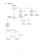
Page 23: ...7 4 No Picture 23 ...
Page 38: ...38 ...
Page 39: ...11 Block Diagram 11 1 Main Block Diagram 39 ...
Page 40: ...11 2 Block 1 5 Diagram 40 ...
Page 41: ...Block 2 5 Diagram ...
Page 42: ...11 4 Block 3 5 Diagram г а P O W E R S U P P LY 42 ...
Page 44: ...11 6 Block 5 5 Diagram S C S C A N D R IV E 44 ...
Page 45: ......
Page 47: ...12 3 Wiring 2 46 ...
Page 48: ...12 5 Wiring 4 12 6 Wiring 5 47 ...
Page 49: ...12 7 Wiring 6 48 ...
Page 52: ...13 2 P MAIN Board 1 3 Schematic Diagram 50 ...
Page 53: ...13 3 P MAIN Board 2 3 Schematic Diagram A B C D E F i 2 3 4 5 6 7 51 ...
Page 55: ...13 5 P SUB Board Schematic Diagram 53 ...
Page 57: ...13 7 A Board 2 25 Schematic Diagram A A BOARD 2 25 Peaks DEST 55 ...
Page 61: ...41 4 2 4 3 4 4 4 5 58 ...
Page 63: ...A A BOARD 7 25 GenX8 13 12 A Board 7 25 Schematic Diagram 5 5 5 6 5 7 5 8 5 9 60 ...
Page 64: ...60 61 62 6 3 ...
Page 67: ...Peaks Com mon 7 8 79 8 0 81 ...
Page 69: ...86 8 7 88 89 9 0 63 ...
Page 76: ...131 1 3 2 1 3 3 1 3 4 13 5 68 ...
Page 85: ...IC 5 5 0 0 C0DBAYY0071 5 2 0 4 2 0 5 2 0 6 2 0 7 ...
Page 89: ...5 1 6 1 7 1 8 1 9 79 ...
Page 90: ...13 32 D Board 2 5 Schematic Diagram 10 1 11 1 12 1 13 1 14 1 15 1 16 1 1 7 1 18 80 ...
Page 91: ...13 33 D Board 3 5 Schematic Diagram 19 1 2 0 1 21 1 2 2 1 2 3 1 2 4 1 2 5 1 2 6 1 2 7 81 ...
Page 92: ...13 34 D Board 4 5 Schematic Diagram 2 8 2 9 30 31 32 3 3 3 4 3 5 3 6 82 ...
Page 93: ...13 35 D Board 5 5 Schematic Diagram 37 38 3 9 4 0 41 4 2 4 3 4 4 4 5 83 ...
Page 94: ...13 36 C1 Board Schematic Diagram A B C D E A C1 BOARD TXNC11LPUJ C20 F 1 2 3 4 5 84 ...
Page 97: ...13 39 C3 Board 1 2 Schematic Diagram F 1 2 3 4 5 87 ...
Page 98: ...13 40 C3 Board 2 2 Schematic Diagram A 10 I 11 12 13 14 C3 BOARD TXNC31 LPUJ 2 2 88 ...
Page 99: ...15 16 17 18 ...
Page 100: ...13 41 C4 Board Schematic Diagram A B C D E A C4 BOARD TXNC41LPUJ C50 F 1 2 3 89 ...
Page 103: ...13 44 C6 Board 1 2 Schematic Diagram A C6 BOARD TXNC61LPUJ 1 2 A 92 ...
Page 105: ...ь fbtq CA14 1 ь I CA15 я 15 16 17 18 ...
Page 107: ...13 47 SC Board 2 4 Schematic Diagram 10 I 11 1 12 1 13 1 14 1 1 5 1 16 1 17 1 18 95 ...
Page 108: ...13 48 SC Board 3 4 Schematic Diagram 19 1 2 0 1 21 1 2 2 1 2 3 1 2 4 1 2 5 1 2 6 1 2 7 96 ...
Page 109: ...13 49 SC Board 4 4 Schematic Diagram 2 8 2 9 3 0 31 3 2 3 3 3 4 3 5 3 6 97 ...
Page 115: ...P MAIN BOARD COMPONENT SIDE ETX2MM813MDM 6 5 4 3 2 1 A I B I C I D I E I F I G I H I I 102 ...
Page 119: ...14 4 A Board A BOARD FOIL SIDE A PR65VT20 т а B G 6 5 4 3 2 1 E F H 106 ...
Page 120: ...A BOARD COMPONENT SIDE A PR65VT20 6 5 4 3 2 1 A I B I C I D I E I F I G I H I I 107 ...
Page 121: ...14 5 D Board 108 ...
Page 122: ...6 D BOARD COMPONENT SIDE TZTNP01LCUE A I В I С I D ...
Page 123: ......
Page 124: ...14 6 C1 Board C1 BOARD COMPONENT SIDE TXNC11LPUJ 1 A I B I C I D I E I F I G I H I I 110 ...
Page 126: ...14 8 C3 Board C3 BOARD FOIL SIDE TXNC31LPUJ 6 5 4 3 1 A I B I C I D I E I F I G I H I I 112 ...
Page 127: ...14 9 C4 Board 113 ...
Page 129: ...14 11 C6 Board 3 C6 BOARD COMPONENT SIDE TXNC61LPUJ 1 A I B I C I D I E I F I G I H I I 115 ...
Page 130: ...14 12 SC Board SC BOARD FOIL SIDE TXNSC1LPUJ В 116 ...
Page 131: ......
Page 132: ... SC BOARD COMPONENT SIDE TXNSC1LPUJ 6 5 4 3 2 1 A I B I C I D I E I F I G I H I I 117 ...
Page 133: ...14 13 SS Board 1 A I B I C I D I E I F I G I H I I 118 ...
Page 134: ...1 A I B I C I D I E I F I G I H I I 119 ...
Page 137: ...15 1 2 Exploded View 2 122 ...
Page 138: ...123 ...
Page 139: ...15 1 4 Packing 2 124 ...

