


3.9.
Rear Cover (Bottom)
1. Remove (16) screws.
2. Remove (1) screw.
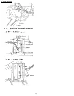
3.10. Disassembly For CRT Removal
To facilitate CRT replacement, the complete CRT mounting
chassis does not need to be removed.
1. Remove the Screen Frame Ass´y, Decorative Panel and
the Bottom Rear Cover Ass´y. ( See Disassemble for
Service ).
2. Unplug the defective CRT Dag ( GND ), from the CRT
Board, LBGND for LB, LGGND for LG, LRGND for LR.
3. Remove lead wires ( DY, VM coil ) and anode lead wire
from holders as necessary.
4. Remove the CRT Board from the defective CRT neck.
5. Note position of yoke with centering tabs and remove from
defective CRT.
6. From the Top, remove (2) screws from the defective CRT.
9
TX-47P800HQ / TX-47P800HZ
Summary of Contents for TX-47P800HQ TX-47P800HZ
Page 15: ...15 TX 47P800HQ TX 47P800HZ ...
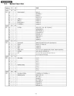
Page 16: ...6 3 Option Descrition 16 TX 47P800HQ TX 47P800HZ ...
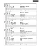
Page 17: ...17 TX 47P800HQ TX 47P800HZ ...
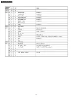
Page 18: ...18 TX 47P800HQ TX 47P800HZ ...
Page 41: ...Fine Convergence Control Chart 41 TX 47P800HQ TX 47P800HZ ...
Page 42: ...42 TX 47P800HQ TX 47P800HZ ...
Page 44: ...11 4 Location of Lead Wiring 4 44 TX 47P800HQ TX 47P800HZ ...
Page 48: ...11 6 Location of Lead Wiring 6 11 7 Location of Lead Wiring 7 48 TX 47P800HQ TX 47P800HZ ...
Page 49: ...11 8 Location of Lead Wiring 8 11 9 Location of Lead Wiring 9 49 TX 47P800HQ TX 47P800HZ ...
Page 50: ...50 TX 47P800HQ TX 47P800HZ ...


