Unpacking and Repacking the Plasma Panel
Panel Replacement Precautions
Handling
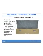
Use extreme care when handling the Plasma Display Panel. Due to the size and
fragility, it is recommended that two individuals handle the Plasma Panel to avoid
accidental damage.
The glass used in the plasma panel is thin, and its structure is extremely susceptible to
impact. Rough handling of the unit can crack the glass or cause pixel defect errors. Be
sure to transport the panel in the upright position. The unit is designed to absorb force
vertically not horizontally.
Numerous flexible printed leads with extremely soft structure are used around the panel.
Be very careful during handling not to damage these by pulling, bending, or subjecting
them to excessive force. When inserting a ribbon cable into a socket, verify that the
cable is straight. Angled insertion can create an electrical short circuit and permanently
damage the panel.
High Voltage
Plasma Display Panels use a high voltage power supply. Disconnect the AC from the
unit and wait one minute for the voltage to dissipate.
Static
Anti-static measures should be applied, especially when connecting and disconnecting
the ribbon cables.
Scratches
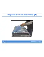
A protective sheet is attached to the back of the replacement panel to prevent scratches
and accumulation of debris. Be sure to remove the protective sheet and wipe the
surface with a soft cloth before installation.
Assembly
A low torque setting is recommended when installing screws in the panel assembly.
Preparation of the new panel
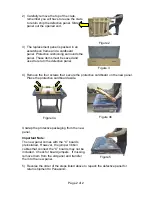
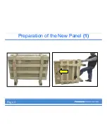
1) The replacement panel is shipped in a special
shipping crate. Retain this crate to return the
defective panel.
Figure 1
Page 1 of 2
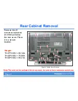
Summary of Contents for TH-42PX50U
Page 1: ...Panel Replacement Procedure TH 37PX50U TH 42PD50U TH 42PX50U...
Page 11: ...Preparation of the New Panel 1 Page 2...
Page 13: ...Preparation of the New Panel 3 Page 3...
Page 14: ...Preparation of the New Panel 4 Page 3...
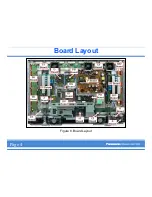
Page 16: ...Board Layout Figure 8 Board Layout Page 4...
Page 31: ...Lead Dressing Figure 39 Lead Dressing Location Page 20...
Page 38: ...I2C Mode Menu Structure B Page 32...
Page 42: ...PDP White Balance Adjustment Step 2 Adjust the Sub Bright Setting to 10cd m2 Page 34...
Page 56: ...Examples Of Defective Panels Horizontal and Vertical error Page 37...
Page 57: ...Examples Of Defective Panels 2 Errors Changing Not a Full Width Page 38...
Page 58: ...Examples Of Defective Panels 3 Errors in 2 places Errors Changing Page 38...
Page 60: ...Panel Replacement Procedure...

