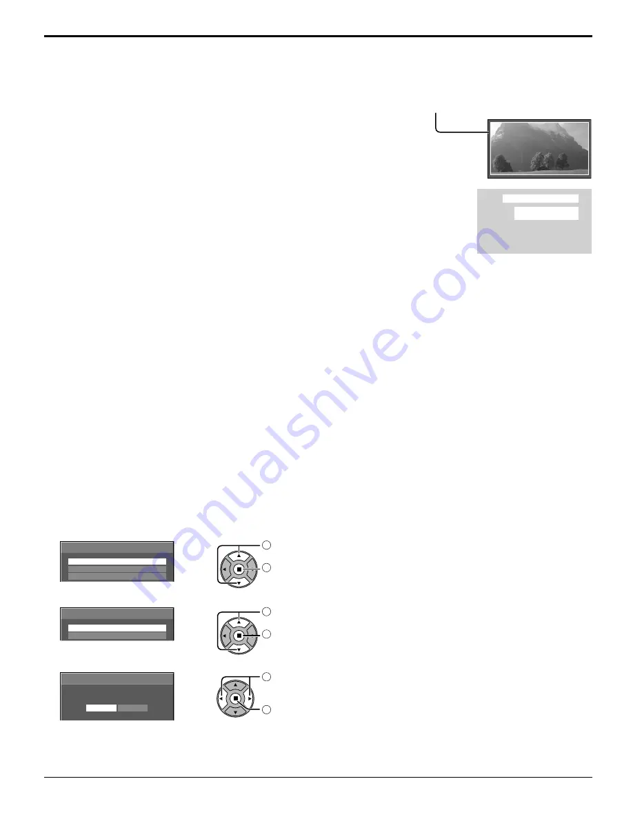
background image

30

Reduces screen image retention

EXPRESS SETTINGS

Set the “Image Retention Reduction” menu to the recommended settings.
All menus will be locked.
   PICTURE MENU: STANDARD
      PICTURE: Recommended setting for each model
   SIDE BAR ADJUST: BRIGHT
   NANODRIFT SAVER: MID
   PEAK LIMIT: ON

1

Select “EXPRESS SETTINGS”.

EXPRESS SETTINGS

CUSTOM SETTINGS

RESET

EXTENDED LIFE SETTINGS

1

 select

2

 access

2

Select the input to apply the settings.

APPLY TO CURRENT INPUT

APPLY TO ALL INPUTS

EXTENDED LIFE SETTINGS

1

 select

2

 set

3

Select “YES”.

APPLY TO CURRENT INPUT

NO

YES

EXTENDED LIFE SETTINGS

1

 select

2

 set

PEAK LIMIT


ON:

  Suppresses image contrast (peak brightness).

Note:

 When a still picture is viewed for an extended time, the screen may become slightly darker. (see page 46)

NANODRIFT SAVER

Moves the display position of the screen slightly to reduce image retention on the display panel. 
   

LOW-HIGH:  

NANODRIFT SAVER operates. The display position of the screen moves at set time intervals. You can set 
the screen movement range. Some of the screen may appear to be missing as a result of this operation. 
If you change the value, a mask is displayed in the range where the picture is missing as a result of position 
movement.

                       When “NANODRIFT” Image Retention Reduction is operating, “NANODRIFT” is 

displayed.

Note:

This function does not work in the following cases.
  When “MULTI DISPLAY SETUP” is set to “ON”
  When in digital zoom mode

PC

FULL

NANODRIFT

Summary of Contents for TH-42PH30U

Page 1: ...PH30U Model No Operating Instructions High Definition Plasma Display English Before connecting operating or adjusting this product please read these instructions completely Please keep this manual for future reference ...

Page 2: ... or shock hazard do not expose this apparatus to rain or moisture Do not place containers with water flower vase cups cosmetics etc above the set including on shelves above etc WARNING 1 To prevent electric shock do not remove cover No user serviceable parts inside Refer servicing to qualified service personnel 2 Do not remove the grounding pin on the power plug This apparatus is equipped with a t...

Page 3: ...ent of the obsolete outlet 10 Protect the power cord from being walked on or pinched particularly at plugs convenience receptacles and the point where they exit from the apparatus 11 Only use attachments accessories specified by the manufacturer 12 Use only with the cart stand tripod bracket or table specified by the manufacturer or sold with the apparatus When a cart is used use caution when movi...

Page 4: ...ction 11 PC Input Terminals connection 12 SERIAL Terminals connection 13 Power ON OFF 14 Selecting the input signal 16 Basic Controls 17 ASPECT Controls 19 Digital Zoom 20 On Screen Menu Displays 21 Adjusting POS SIZE 22 PICTURE Adjustments 24 ADVANCED SETTINGS 25 SOUND Adjustment 26 SCREENSAVER For preventing image retention 27 Setup of SCREENSAVER Time 28 Reduces screen image retention 29 EXTEND...

Page 5: ...ce that may cause undesired operation FCC CAUTION To assure continued compliance follow the attached installation instructions and use only shielded interface cables when connecting to computer or peripheral devices Any changes or modifications not expressly approved by Panasonic Corp of North America could void the user s authority to operate this device FCC Declaration of Conformity Model No TH ...

Page 6: ...sty Built up dust on the power cord plug can increase humidity which might damage the insulation and cause fire Unplug the cord from the wall outlet and clean it with a dry cloth This Plasma Display radiates infrared rays therefore it may affect other infrared communication equipment Install your infrared sensor in a place away from direct or reflected light from your Plasma Display Note Do not al...

Page 7: ...d 2 3 4 7 cm or more at the rear and also keep the space between the bottom of the display and the floor surface If using some other setting up method follow the manual of it If there is no specific indication of installation dimension in the installation manual leave a space of 3 15 16 10 cm or more at the top bottom left and right and 2 3 4 7 cm or more at the rear When installing the Plasma Dis...

Page 8: ...pt to charge short circuit disassemble heat or burn used batteries 5 Battery replacement is necessary when the remote control acts sporadically or stops operating the Plasma Display 6 Do not burn or breakup batteries Batteries must not be exposed to excessive heat such as sunshine fire or the like 3 Replace the cover Accessories Supplied Check that you have the Accessories and items shown Operatin...

Page 9: ...essing the two knobs Note When disconnecting theAC cord be absolutely sure to disconnect theAC cord plug at the socket outlet first AC cord connection and fixing cable fixing Speaker connection Red Black While pressing the lever insert the core wire Red Black Return the lever Connections When using the Wall hanging bracket vertical Note When using the Wall hanging bracket vertical TY WK42PV20 use ...

Page 10: ...r Connections Video equipment connection AV IN VIDEO Composite Video Input Terminal see below COMPONENT RGB IN Component RGB Video Input Terminal see below AV IN HDMI HDMI Input Terminal see page 11 DVI D IN DVI D Input Terminal see page 11 Connect to video equipment such as VCR or DVD player PC IN PC Input Terminal Connect to video terminal of PC or equipment with Y PB CB and PR CR output see pag...

Page 11: ...layer HDMI cable Stereo mini plug M3 DVI video cable Within 5 m PC with DVI D video out Pin No Signal Name Pin No Signal Name 1 T M D S data 2 13 2 T M D S data 2 14 5 V DC 3 T M D S data 2 shield 15 Ground 4 16 Hot plug detect 5 17 T M D S data 0 6 DDC clock 18 T M D S data 0 7 DDC data 19 T M D S data 0 shield 8 20 9 T M D S data 1 21 10 T M D S data 1 22 T M D S clock shield 11 T M D S data 1 s...

Page 12: ... time of connection Some PC models cannot be connected to the set There is no need to use an adapter for computers with DOS V compatible Mini D sub 15P terminal The computer shown in the illustration is for example purposes only Additional equipment and cables shown are not supplied with this set Do not set the horizontal and vertical scanning frequencies for PC signals which are above or below th...

Page 13: ... 03h STX C1 C2 C3 P1 P2 P3 P4 P5 ETX Notes If multiple commands are transmitted be sure to wait for the response for the first command to come from this unit before sending the next command If an incorrect command is sent by mistake this unit will send an ER401 command back to the computer Pin layout for SERIAL Terminal Command Parameter Control details PON None Power ON POF None Power OFF AVL Vol...

Page 14: ...ch on the Plasma Display to turn the set on Power On Power Indicator Green Press the button on the remote control to turn the Plasma Display off Power Indicator Red standby Press the button on the remote control to turn the Plasma Display on Power Indicator Green Turn the power to the Plasma Display off by pressing the switch on the unit when the Plasma Display is on or in standby mode Note During...

Page 15: ...elieve you of it See page 44 NO ACTIVITY POWER OFF IS ENABLED When first switching on the unit Following screen will be displayed when the unit is turned on for the first time Select the items with the remote control Unit buttons are invalid OSD LANGUAGE DISPLAY ORIENTATION 1 Select the language 2 Set 1 For vertical installation select PORTRAIT 2 Set Notes Once the items are set the screens won t ...

Page 16: ...in PC IN COMPONENT may be displayed as RGB depending on the setting of COMPONENT RGB IN SELECT see page 37 Notes Selecting is also possible by pressing the INPUT button on the unit Outputs the sound as set in Audio input select in the Options menu see page 45 Select to match the signals from the source connected to the component RGB input terminals see page 37 Image retention image lag may occur o...

Page 17: ... will still consume some power as long as the power cord is still inserted into the wall outlet Standby Red Power ON Green PC POWER MANAGEMENT DPMS Orange With PC input signal See page 32 DVI D POWER MANAGEMENT Orange With DVI input signal See page 32 Volume Adjustment Volume Up Down When the menu screen is displayed press to move the cursor up press to move the cursor down see page 21 Enter Aspec...

Page 18: ...tton Automatically adjusts the position size of the screen see page 22 SET UP button see page 21 SOUND button see page 26 Volume Adjustment Press the Volume Up or Down button to increase or decrease the sound volume level R button see page 21 Press the R button to return to previous menu screen OFF TIMER button The Plasma Display can be preset to switch to stand by after a fixed period The setting...

Page 19: ...al input 1125 1080 60i 50i 60p 50p 24p 25p 30p 24sF 750 720 60p 50p All Aspect mode Set All Aspect to On in Options menu to enable the extended aspect mode page 44 When All Aspect mode the aspect mode of pictures is switched as follows For details about the aspect mode please see List of Aspect Modes page 47 For VIDEO signal input Note Be aware that if you put the display in a public place for com...

Page 20: ...le in the following operation state When MULTI DISPLAY SETUP is ON see page 35 When SCREENSAVER except for NEGATIVE IMAGE is running see page 27 While Digital Zoom is in operation Adjusting POS SIZE cannot be used Select the magnification required for the enlarged display Each time this is pressed the magnification factor changes This is shown in the image being displayed 3 2 4 The cursor will mov...

Page 21: ...see page 22 23 see page 26 SET UP menu POS SIZE menu SOUND menu 25 0 0 0 5 PICTURE NORMAL NORMALIZE STANDARD BRIGHTNESS SHARPNESS PICTURE MENU COLOR PICTURE TINT COLOR MANAGEMENT ADVANCED SETTINGS COLOR TEMP NORMAL OFF 1 2 SIGNAL EXTENDED LIFE SETTINGS INPUT LABEL SET UP OFF ON OFF ENABLE DISABLE OSD LANGUAGE ENGLISH US COMPONENT RGB IN SELECT RGB SCREENSAVER PC POWER MANAGEMENT DVI D POWER MANAGE...

Page 22: ... a PC signal as an example H POS V POS H SIZE V SIZE DOT CLOCK and CLOCK PHASE are automatically corrected This setting is enabled under the following conditions This setting is not activated during Multiple display or Digital Zoom When inputting an analog signal Component PC This setting is enabled if COMPONENT RGB IN SELECT see page 37 in SET UP menu is RGB When inputting a digital signal HDMI D...

Page 23: ...525i 525p 625i 625p 750 60p 750 50p 1125 60i 1125 50i 1125 24sF 1125 25p 1125 24p 1125 60p 1125 50p 1125 30p Component Video RGB DVI HDMI ON OFF Notes When OFF is set H SIZE and V SIZE cannot be adjusted When the Display size is set to On in the Options menu this setting will be invalid see page 43 Adjusting POS SIZE Notes If the dot clock frequency of an analog signal is 108 MHz or higher DOT CLO...

Page 24: ... a professional level see next page COLOR MANAGEMENT ON Enables vivid color adjustment automatically While the PICTURE menu is displayed if either the N button on the remote control is pressed at any time or the ACTION button is pressed during NORMALIZE then all adjustment values are returned to the factory settings Helpful Hint NORMALIZE Normalization Press the left or right button to switch betw...

Page 25: ...re Adjusts picture sharpness Item Effect Details BLACK EXTENSION Less More Adjusts the dark shades of the image in gradation INPUT LEVEL Less More Adjustment of parts which are extremely bright and hard to see GAMMA Down Up S CURVE 2 0 2 2 2 6 W B HIGH R Less More Adjusts the white balance for light red areas W B HIGH G Less More Adjusts the white balance for light green areas W B HIGH B Less More...

Page 26: ...exit from adjust mode 2 Select to adjust each item While the SOUND menu is displayed if either the N button on the remote control is pressed at any time or the ACTION button is pressed during NORMALIZE then all adjustment values are returned to the factory settings Helpful Hint NORMALIZE Normalization 3 Item Details AUDIO MENU STANDARD Emits the original sound DYNAMIC Accentuates sharp sound BASS ...

Page 27: ...DE is set to ON press to select START Press to start SCREENSAVER The menu screen will disappear and the SCREENSAVER will be activated To stop the SCREENSAVER under ON press the R button or any buttons on the main unit Note When the display is turned off the SCREENSAVER will be deactivated Press to select the MODE Press to select each mode items SCREENSAVER For preventing image retention Off INTERV...

Page 28: ...ting Time may be set Time cannot be set when MODE is ON or OFF Press to select SHOW DURATION SAVER DURATION When INTERVAL is selected Press to select SCREENSAVER DURATION When STANDBY AFTER SCR SAVER is selected Press to setup button Forward button Back Notes Pressing or button once changes the Time 1 minute However switching occurs every 15 minutes when Periodic Time is selected Pressing or butto...

Page 29: ...lluminate the side bars This function may be applicable to the non picture area OFF Darken both ends DARK Make it dark gray MID Make it gray BRIGHT Make it light gray Notes To reduce the occurrence of image retention set the SIDE BAR ADJUST to BRIGHT The side bar may flash alternate black white depending on the picture being shown on the screen Using Cinema mode will reduce such flashing side bars...

Page 30: ...ses image contrast peak brightness Note When a still picture is viewed for an extended time the screen may become slightly darker see page 46 NANODRIFT SAVER Moves the display position of the screen slightly to reduce image retention on the display panel LOW HIGH NANODRIFT SAVER operates The display position of the screen moves at set time intervals You can set the screen movement range Some of th...

Page 31: ...LY TO CURRENT INPUT APPLY TO ALL INPUTS OFF 30 RECOMMENDED SETTINGS 1 select 2 adjust Whenamenuislocked itisgrayedoutandcannotbeset PICTURE MENU and PICTURE will no longer be able to set in the PICTURE menu and they are labeled with icon to indicate their locked status 0 0 0 5 PICTURE NORMAL NORMALIZE DYNAMIC BRIGHTNESS SHARPNESS PICTURE MENU COLOR PICTURE TINT COLOR MANAGEMENT ADVANCED SETTINGS C...

Page 32: ...COMPONENT RGB IN SELECT is set to RGB and during normal viewing one picture screen DVI D POWER MANAGEMENT When this function is set to ON it operates under the following conditions to turn the power on or off automatically When no pictures sync signal are detected for 30 or so seconds during DVI signal input Power is turned off standby the power indicator lights up orange When pictures sync signal...

Page 33: ...NT HDMI DVI PC This function can change the label of the Input signal to be displayed see page 16 Image input Input label VIDEO VIDEO DVD1 DVD2 DVD3 Blu ray1 Blu ray2 Blu ray3 CATV VCR STB SKIP COMPONENT COMPONENT DVD1 DVD2 DVD3 Blu ray1 Blu ray2 Blu ray3 CATV VCR STB SKIP HDMI HDMI DVD1 DVD2 DVD3 Blu ray1 Blu ray2 Blu ray3 CATV VCR STB SKIP DVI DVI DVD1 DVD2 DVD3 Blu ray1 Blu ray2 Blu ray3 CATV V...

Page 34: ... a fan LANDSCAPE PORTRAIT Fan control and panel drive control for horizontal installation Fan control and panel drive control for vertical installation On screen menu will be rotated 90 degrees counterclockwise to be suitable for the setting DISPLAY ORIENTATION Press to display the SET UP menu Press to select OSD LANGUAGE Press to select your preferred language Selectable languages Japanese Chines...

Page 35: ...EAM HIDES VIDEO 2 MULTI DISPLAY SETUP SET UP for MULTI DISPLAY Example group of 25 5 5 Press to display the SET UP menu 1 2 3 Press to select the MULTI DISPLAY SETUP Press to select ON or OFF Item Details MULTI DISPLAY SETUP Select ON or OFF HORIZONTAL SCALE Select 1 2 3 4 5 VERTICAL SCALE Select 1 2 3 4 5 SEAM HIDES VIDEO Select ON or OFF To hide joints between displays Suitable for moving image ...

Page 36: ...umber button is pressed more than two times the first two numbers become the ID number for the remote control ID Cancellation Press button on remote control This has the same effect as pressing the buttons at the same time Notes Set the Remote ID On to operate the ID remote control If Remote ID is set to On you can use the remote control without identical ID number during option menu display see p...

Page 37: ...IN SELECT Select to match the signals from the source connected to the Component RGB or PC input terminals Y PB PR signals COMPONENT RGB signals RGB Press to display the SET UP menu Press to select the COMPONENT RGB IN SELECT Press to select the desired mode COMPONENT RGB Press to exit from adjust mode Note Make setting of the selected input terminal COMPONENT RGB IN or PC IN 1 2 3 YUV RGB IN SELE...

Page 38: ... XGA MODE AUTO NOISE REDUCTION OFF H FREQ V FREQ kHz Hz 63 98 60 02 SIGNAL FORMAT 1280 1024 60 SYNC 3 2 PULLDOWN AUTO OFF SYNC SIGNAL H FREQ V FREQ kHz Hz 63 98 60 02 SIGNAL FORMAT 1280 1024 60 RGB 3 2 PULLDOWN XGA MODE NOISE REDUCTION OFF AUTO OFF AUTO 38 Press to select the menu to adjust Press to adjust the menu Press to exit from adjust mode Note SIGNAL setup menu displays a different setting ...

Page 39: ...ects the following signal input NTSC PAL signal input during VIDEO input signal 525i 480i 625i 575i 1125 1080 60i signal input during COMPONENT input signal XGA MODE This menu is displayed when the input signal is analog Component PC This unit supports three types of XGA signals with 60Hz vertical frequency having different aspect ratios and sampling rates 1 024 768 60Hz 1 280 768 60Hz and 1 366 7...

Page 40: ...osquito noise around subtitles on MPEG videos BLOCK NR Reduces block noise when playing MPEG videos Note NOISE REDUCTION cannot be adjusted while a PC signal is being applied SET UP for Input Signals NOISE REDUCTION Sets the following three NR Noise Reduction functions together VIDEO NR MOSQUITO NR BLOCK NR Press to select NOISE REDUCTION Press to select OFF MIN MID MAX ADVANCED Sets the three NR ...

Page 41: ...to RGB input this setting is valid only for RGB input signal AUTO The H and V sync or synchronized signal is automatically selected If both input it is selected the H and V sync ON G Uses a synchronized signal on the Video G signal which is input from the G connector Setting Component sync signal Confirm that the input is set to Component input this setting is valid only for Component input signal...

Page 42: ...displayed see page 16 This menu is available only when Input lock is Off Initial VOL level Press button to adjust the volume when the unit is turned on Off On Off Sets normal volume On Sets your preferred volume Notes When Maximum VOL level is On the volume can only be adjusted between 0 and your maximum range You can hear the changed volume regardless of your volume setting before opening the opt...

Page 43: ...s the same state as before the power interruption Standby Power returns in standby mode Power Indicator red orange On Power returns in power On Power Indicator green Note When using multiple displays Standby is preferred to be set in order to reduce a power load ID select Sets panel ID number when panel is used in Remote ID or Serial ID Set value range 0 100 Standard value 0 Remote ID The setting ...

Page 44: ...lected mode Off Default aspect mode On All Aspect mode Aspect mode of each setting is as follows Example HD signal Off 4 3 H FILL ZOOM FULL JUST On 4 3 1 4 3 2 4 3 Full Zoom1 Zoom2 Zoom3 16 9 14 9 Just1 Just2 Auto Setup Sets the operational mode of the automatic position adjustment in the POS SIZE menu Manual Automatic position adjustment starts when is pressed on the remote control or automatic p...

Page 45: ...anel mode Calibration mode Touch Panel settings On Touch Panel mode Calibration mode Touch Panel settings On The screen is displayed in the middle and NANODRIFT is deactivated for 180 seconds After 180 seconds or when you have the menu displayed with a remote control Calibration mode is cancelled Note For information on how to set up Calibration please see Touch Panel instruction manual The mode t...

Page 46: ...POWER OFF and NO ACTIVITY POWER OFF in the SET UP menu Any of them may be set to ON ENABLE see page 32 Power indicator is blinking in red There is possibility of malfunction Please contact an Authorized Service Center This Plasma Display uses special image processing Hence a slight time lag may occur between image and audio depending on the type of input signal However this is not a malfunction Pl...

Page 47: ...e areas around the left and right edges of the screen is slightly elongated 4 3 4 3 Pictures with a 4 3 aspect ratio are displayed with their original aspect ratio Side panels are displayed at the left and right edges of the screen 4 3 1 4 3 2 4 3 Pictures with a 4 3 aspect ratio are displayed with their original aspect ratio The left and right edges of the pictures are masked by side panels 4 3 F...

Page 48: ...24 28 1 024 768 50 Hz 39 55 50 00 51 89 29 1 024 768 60 Hz 48 36 60 00 65 0 65 0 30 1 024 768 70 Hz 56 48 70 07 75 0 31 1 024 768 75 Hz 60 02 75 03 78 75 32 1 024 768 85 Hz 68 68 85 00 94 5 33 1 066 600 60 Hz 37 64 59 94 53 0 53 0 34 1 152 864 60 Hz 53 70 60 00 81 62 35 1 152 864 75 Hz 67 50 75 00 108 0 36 1 280 768 60 Hz 47 70 60 00 80 14 37 1 280 960 60 Hz 60 00 60 00 108 0 38 1 280 960 85 Hz 85...

Page 49: ... Press to display the Shipping menu Press to select YES Press to confirm from the unit 1 Press the MENU button till the SET UP menu is displayed 2 Press the Volume Up or Down button to select OSD LANGUAGE 3 Press and hold the ENTER button till the Shipping menu is displayed 4 Press the Volume Up or Down button to select YES 5 Press the ENTER button and wait for 10 sec 6 Turn the power off 2 3 Opti...

Page 50: ...l scanning frequency 48 120 Hz Connection terminals AV IN VIDEO AUDIO L R BNC RCA Pin jack 2 1 0 Vp p 75 Ω 0 5 Vrms HDMI TYPE A Connector COMPONENT RGB IN Y G PB CB B PR CR R AUDIO L R BNC BNC BNC RCA Pin jack 2 with sync 1 0 Vp p 75 Ω 0 7 Vp p 75 Ω 0 7 Vp p 75 Ω 0 5 Vrms DVI D IN AUDIO DVI D 24 Pin Content Protection Stereo mini jack M3 1 Compliance with DVI Revision 1 0 Compatible with HDCP 1 1 ...

Page 51: ... should note this serial number in the space provided below and retain this book plus your purchase receipt as a permanent record of your purchase to aid in identification in the event of theft or loss and for Warranty Service purposes Model Number Serial Number Panasonic Corporation 2011 USA Only Disposal may be regulated in your community due to Environmental considerations For disposal or recyc...

Reviews: