background image

15

English

Identifying Controls

Main unit

● 

To take out/store the power indicator and remote 

control sensor, operate the lever on the rear panel.
It is also possible to press the remote control 

sensor directly to store.

Note

● 

For normal use, pull out the power indicator and 

remote control sensor from the edge side of the 

main unit by operating the lever on the rear panel. 

Depending on the setup condition such as when 

using the multi display, store them in the main unit.

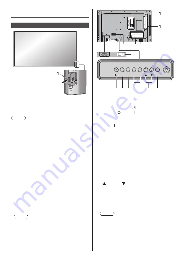
1  Power Indicator / Remote control sensor

The Power Indicator will light.

When the power of the unit is ON (Main Power On 

/ Off button: ON)

● 

Picture is displayed: Green

● 

When the unit enters the standby mode using the 

following functions: Orange (Red/Green)

 •

Standby state with the “Power management” 

function

 •

Standby state with [HDMI-CEC control] set to 

[Enable] and at least one [Link function] set to 

other than [Disable]

 •

Standby state with [Network control] set to [On]

● 

Standby state in conditions other than the above: 

Red

When the power of the unit is OFF (Main Power 

On / Off button: OFF): No light

Note

● 

Even if the unit is turned off with the power indicator 

off, some of the circuits are in power-on status.

● 

When the power indicator is orange, power 

consumption during standby is generally larger than 

that of when the power indicator is red.

MENU

ENTER

INPUT

+

-

9

1

2

9

3 4 5

6

7

8

1  External Input Terminal

Connects to video equipment, PC, etc. (see page 13)

2  Main power switch ( 

 ) (Unit)

Turns OFF (   ) or ON (  ) the main power.
Turning ON and OFF the <Main power switch> is the 

same as plugging and unplugging the power plug.
Turn ON (  ) the main power first, and then turn 

OFF or ON the power using the Power button of the 

remote control or the unit.

3 <Main Power On / Off button>

Turns the power Off / On.

4 <INPUT (Unit)>

Selects the connected device.

5 <MENU (Unit)>

Displays the menu screen.

6 <+ (Unit)> / <- (Unit)>

Adjusts the volume.
On the main screen, switches settings or adjusts 

settings level.

7 <   (Unit)> / <   (Unit)>

Selects the setting item on menu screen.

8 <ENTER (Unit)>

Configures the item on menu screen.
Switches aspect mode.

9  Built-in speakers

Note

● 

To output sound from the built-in speakers of the 

unit, be sure to set [Output select] in the [Sound] 

menu to [SPEAKERS].

Summary of Contents for TH-32EF2U

Page 1: ...9 Software License 21 PANASONIC PROFESSIONAL DISPLAY Limited Warranty 22 Read before use For more information about this product please read the Operating Instructions Functional Manual To download th...

Page 2: ...tions 5 Do not use this apparatus near water 6 Clean only with dry cloth 7 Do not block any ventilation openings Install in accordance with the manufacturer s instructions 8 Do not install near any he...

Page 3: ...ll applicable IC RSS standards Operation is subject to the following two conditions 1 This device may not cause harmful interference and 2 this device must accept any interference received including i...

Page 4: ...display in an unstable location A display may fall causing serious personal injury or death Many injuries particularly to children can be avoided by taking simple precautions such as Using cabinets or...

Page 5: ...g the unit with its display panel facing upright or downward may cause damage to the internal circuitry Ventilation should not be impeded by covering the ventilation openings with items such as newspa...

Page 6: ...plug from the wall outlet and wipe it with a dry cloth Do not handle the power supply plug with wet hands Doing so may cause electric shocks Securely insert the power supply plug socket outlet side a...

Page 7: ...to excessive heat such as sunshine fire or the like Do not turn the Display upside down Do not position the unit with its display panel facing upright Precautions for use Cautions when installing Do...

Page 8: ...be used for any prolonged length of time unplug the power supply plug from the wall outlet When storing the product for long periods with no power supplied do not store it in a location exposed to di...

Page 9: ...cal cloth Do not use a chemical cloth for the liquid crystal panel surface Follow the instructions for the chemical cloth to use it for the cabinet Avoid contact with volatile substances such as insec...

Page 10: ...teries note correct polarity and AAA R03 LR03 type 3 Replace the cover Helpful Hint For frequent remote control users replace old batteries with Alkaline batteries for longer life Precaution on batter...

Page 11: ...11 English Kensington security The security slot of this unit is compatible with the Kensington security slot...

Page 12: ...Fix the cables at location as shown below If you need more clampers purchase them from your dealer Available from the customer service 1 1 For signal cable clamper 1 Attach the clamper Note Wipe off d...

Page 13: ...DVI D output 5 SERIAL IN SERIAL Input Terminal Control the Display by connecting to PC 6 LAN LAN Terminal Control the Display by connecting to Network 7 USB USB Terminal Connect the USB memory to use...

Page 14: ...he external device to the system that is neither supplied with the device nor available as an option If the outer shape of the plug of a connection cable is large it may come in contact with the perip...

Page 15: ...e power of the unit is OFF Main Power On Off button OFF No light Note Even if the unit is turned off with the power indicator off some of the circuits are in power on status When the power indicator i...

Page 16: ...ition size of the screen 11 INPUT Switches input to display on the screen 12PICTURE 13SOUND 14RECALL Displays the current setting status of Input mode Aspect mode etc 15RETURN Used to return to the pr...

Page 17: ...with on screen menu Disconnect the power plug after a enough period of time Or disconnect the power plug after turning the power off with the remote control RS 232C control or LAN control 3 Turn ON t...

Page 18: ...ing menus OSD language Display orientation Power ON message The following message may be displayed when turning the unit power ON No activity power off Precautions No activity power off is enabled Whe...

Page 19: ...onnection terminals HDMI 1 HDMI 2 TYPE A Connector 2 2 Audio signal Linear PCM sampling frequencies 48 kHz 44 1 kHz 32 kHz DVI D IN DVI D 24 Pin 1 Compliance with DVI Revision 1 0 Content Protection C...

Page 20: ...Power source DC 3 V battery AAA R03 LR03 type 2 Operating range Approx 7 m 22 9 ft when operated directly in front of remote control sensor Mass Approx 63 2 22 oz including batteries Dimensions W H D...

Page 21: ...will give to any third party who contacts us at the contact information provided below for a charge no more than our cost of physically performing source code distribution a complete machine readable...

Page 22: ...n shipping failures which are caused by products not supplied by Panasonic failures which result from accident misuse abuse neglect mishandling misapplication alteration modification faulty installati...

Page 23: ...this serial number in the space provided below and retain this book plus your purchase receipt as a permanent record of your purchase to aid in identification in the event of theft or loss and for Wa...

Reviews: