Fig. 17-4.
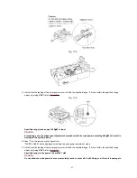
4. Confirm that the reading of the laser power meter is within the specified range. If it is not within the specified range,
adjust by turning
VR1
. Refer to
Fig. 17-5.
Fig. 17-5.
Specified range (read power): 600
µµµµ
W or lower
Caution:
Proceeding on to the subsequent adjustment procedure with the read power exceeding 600
µµµµ
W will result in
damage to the optical pickup.
5. Press “2” on the remote control transmitter.
“WRITE LASER” will be displayed to indicate the write power adjustment mode.
6. Confirm that the reading of the laser power meter is within the specified range. If it is not within the specified range,
adjust by turning
VR1
. Refer to
Fig. 17-5.
Specified range (write power): 4.8 mW±0.1 mW
Caution:
Do not allow the write power to even momentarily reach or exceed 5.5 mW. Doing so will result in damage to
43
Summary of Contents for SJ-MD150
Page 5: ...4 Caution for AC Mains Lead 5 ...
Page 10: ...10 ...
Page 15: ...15 ...
Page 16: ...16 ...
Page 17: ... Check the MD servo P C B B side as shown below 17 ...
Page 19: ...19 ...
Page 20: ...20 ...
Page 21: ...21 ...
Page 22: ...8 7 Replacement for the belt and loading motor Follow the Step 1 Step 3 of item 8 1 22 ...
Page 23: ...23 ...
Page 25: ...25 ...
Page 36: ...30 TEST02 Test terminal Not used open 36 ...
Page 48: ...48 ...
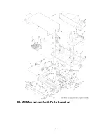
Page 57: ...20 MD Mechanism Unit Parts Location 57 ...
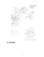
Page 58: ...21 Packaging 58 ...
Page 59: ...F000300000YM KH 59 ...

