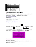
- Do not allow the write power to even momentarily reach or exceed 5.5 mW. Doing so will result in damage to the optical
pickup.
- Do not set the unit to the laser power adjustment mode with the MD loaded. Doing so may result in damage to the MD.
17.3. Laser power adjustment
Adjust each laser power: read power for reading (play) and write power for writing (record).
Caution:
1.
About handling the MD unit
- The magnetic head is precision unit and is very fragile. Do not deform it.
- Laser diode in the optical pickup may be destroyed by the static electricity generated in your clothes or body. Be
especially careful with the static electricity.
- The optical pickup is structured extremely precisely. Do not subject to the strong impact or shock. Do not touch
the lens.
2.
About handling the magnetic head
When replacing the magnetic head, do not tighten the mounting screw (RHD17022) too firmly. If the screw is tightened
too much to deform the resin, the position of the head is moved, and this affects its recording operation.
Recommended torque for mounting screw: / 700±100 g cm
Reference:
This is the same force as using a screwdriver with a 15-mm diameter grip, you fasten the screw naturally with your
thumb and index finger.
3.
About the driver for adjusting laser power
Use only insulated driver such as a ceramic driver. With the metal driver, it is not possible to adjust properly because of
induction noise. Also, if it short-circuits with the chassis, it may destroy or damage the laser diode.
Recommended driver: VESSEL 9000 1.8-30 / (Ceramic driver)
17.3.1. Adjustment Procedure
1. With no MD loaded in the unit , press “1” on the remote control transmitter.
“RAM LASER” will be displayed to indicate the read power adjustment mode.
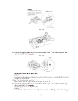
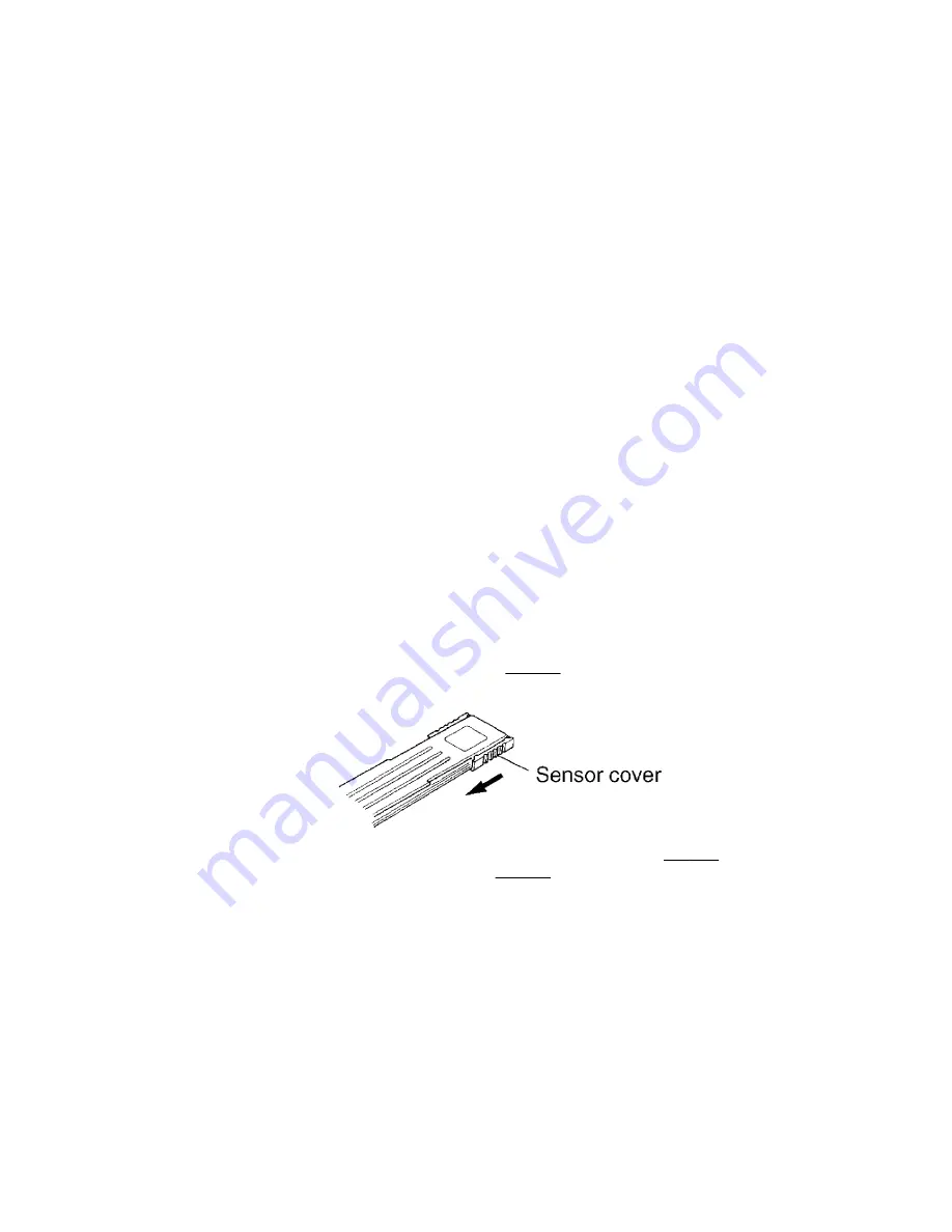
2. Slide the sensor cover of the laser power meter. / Refer to
Fig. 17-2.
Fig. 17-2.
3. Position the sensor of the laser power meter directly above the optical pickup. Refer to
Fig. 17-3.
Or load the cartridge of
the laser power meter into the MD mechanism. Refer to
Fig. 17-4.
Fig. 17-3.
42
Summary of Contents for SJ-MD150
Page 5: ...4 Caution for AC Mains Lead 5 ...
Page 10: ...10 ...
Page 15: ...15 ...
Page 16: ...16 ...
Page 17: ... Check the MD servo P C B B side as shown below 17 ...
Page 19: ...19 ...
Page 20: ...20 ...
Page 21: ...21 ...
Page 22: ...8 7 Replacement for the belt and loading motor Follow the Step 1 Step 3 of item 8 1 22 ...
Page 23: ...23 ...
Page 25: ...25 ...
Page 36: ...30 TEST02 Test terminal Not used open 36 ...
Page 48: ...48 ...
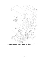
Page 57: ...20 MD Mechanism Unit Parts Location 57 ...
Page 58: ...21 Packaging 58 ...
Page 59: ...F000300000YM KH 59 ...

